Close-range one-to-many wireless charging device and system

A wireless charging, short-distance technology, applied in the direction of circuit devices, battery circuit devices, circuits, etc., can solve the problems of difficult to achieve design power, reduce transmission power, cost complexity, etc., to facilitate large-scale promotion, reduce complexity, Easily extendable effects

Active Publication Date: 2021-05-07
西安电掣风云智能科技有限公司
View PDF7 Cites 0 Cited by
  • Summary
  • Abstract
  • Description
  • Claims
  • Application Information

AI Technical Summary

Problems solved by technology

In addition to cost, complexity, there are issues of weight and handling
In a small wireless charging flat panel, the more complex the splicing of the structure and modules, the more hidden concerns the fine structure has. In addition to the magnetic field application, more plastic materials must be used. This superimposed technology crystallization is less durable
It is easy to generate various fault problems. In order to avoid these problems, manufacturers generally reduce the transmission power, cool down at the level invisible to the user, and increase stability at the same time; making it difficult to reach the design power in practical applications

Method used


Image

  • Close-range one-to-many wireless charging device and system
  • Close-range one-to-many wireless charging device and system
  • Close-range one-to-many wireless charging device and system

Examples


Embodiment 1

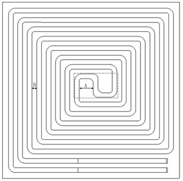
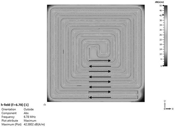
[0037] A short-range one-to-many wireless charging device, including a transmitting coil, which is a single metal wire wound from the outside to the inside, after a short circuit in the central area, it is wound from the inside to the outside in the opposite direction coherently at one time, forming It is similar to the pattern pattern of "wealth and wealth do not reach the end"; this kind of circuit enters in one line and exits in the same line, so that the current direction of each turn and adjacent turns is opposite, such as Figure 1-2 shown.

[0038] The transmitting coil is set on the substrate, and one line is presented coherently at one time. The entire large substrate is a coil loop, unlike Qi, where each coil is passed through a layer of Litz wire, a layer of glue, another layer of magnetic chip, and another layer. A layer of plastic or metal compartments and so on stacked up.

[0039] In some embodiments, figure 1 The central short-circuit area of ​​the middle coi...

Embodiment 2

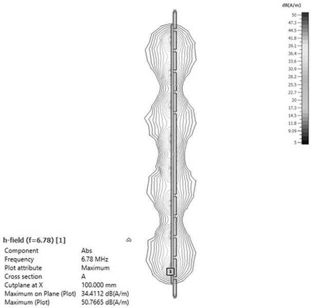
[0043] The surface of the substrate is covered with a metal layer, because the magnetic field is all from the single-sided copper-clad substrate (copper-clad laminate), so the magnetic field passing through the substrate is less, which reduces the influence of the tangential loss of the substrate on the transmission efficiency of the wireless charging device. The thickness of the copper layer is 1-5 ounces (OZ). In some embodiments, the substrate is FR-4 or PCB, both of which can realize high-efficiency power transmission; the surface of the substrate is covered with a metal layer. In some embodiments, the copper clad laminate does not use a solder mask; higher performance can be obtained by immersion silver.

[0044] Embodiment 2 The simulated magnetic field of the wireless charging device whose substrate is a copper clad laminate, such as Figure 4 (Standard positive center cross-section), the black line on the right side of the figure is the metal layer, which separates th...

Embodiment 3

[0047] structured as Figure 9 Shown, the structure of embodiment 3 and embodiment 1,2 is similar, Figure 9 The distance between adjacent coils with opposite medium current direction is 8mm, the line width is 4mm, and the number of turns of the coil wound from outside to inside is 3; the simulation results are as follows Figure 10 (section of the vertical line on the right) as shown, with image 3 , Figure 4 Compared with the simulation results of Figure 10 The magnetic field distribution at the middle edge is smoother.


PUM

PropertyMeasurementUnit
widthaaaaaaaaaa

Abstract

The invention discloses a close-range one-to-many wireless charging device and system. The wireless charging device comprises a transmitting coil arranged on a base body, wherein the transmitting coil is formed by winding a single metal wire from outside to inside, and after a central region is short-circuited, the transmitting coil is continuously wound from inside to outside in an opposite direction at a time; and a one-wire-in and same-ire-out mode is adopted, and the current directions of each turn of lead wire and the adjacent turn of lead wire are opposite. According to the close-range one-to-many wireless charging device and the system, coil superposition is not needed, the size and the weight are reduced to a great extent, a smooth and uniform near field is maintained, and no blind regionexists, so that receiving equipment can be randomly spliced on the charging panel, the cost is greatly reduced, and the control stability, the charging efficiency and the applicability are improved.

Description

technical field [0001] The invention belongs to the technical field of induction power, and relates to a short-distance one-to-many wireless charging device and system. Background technique [0002] The coils used in most existing wireless charging devices mainly use the QI technical standard: composed of tightly wound coils and magnetic cores, using the principle of electromagnetic induction, energy is transmitted through continuous energy coupling of the coils, and the coil and magnetic cores work together to improve transmission efficiency . [0003] At present, the credibility of Qi makes wireless power manufacturers generally use Qi-type coil modules from foreign manufacturers, and they must use Qi-type coil modules as a reference. Even if the coil is customized, it often directly uses the multi-turn coil of the coil manufacturer; It can also be clearly seen from the papers and published patents that most of the technical solutions are based on Qi-type coil modules and...

Claims


Application Information

Patent Timeline
Patent Type & Authority Applications(China)
IPC IPC(8): H02J50/12H02J50/00H02J7/00H01F27/28H01F38/14
CPCH01F27/28H01F27/2804H01F38/14H02J7/0042H02J50/12H02J50/005
Inventor 李谦
Owner 西安电掣风云智能科技有限公司
Why Eureka
Try Eureka