Piezoelectric Energy Harvesting Experimental Device for Flow-Induced Vibration of Film Wing

A test device and vibration pressure technology, which is applied in the direction of measuring devices, aerodynamic tests, and testing electrical devices in transportation, etc., can solve the problem of affecting the aerodynamic performance of film wings, the passive deformation of structures becomes smaller, and the fatigue fracture of piezoelectric sheets, etc. problems, to achieve the effect of improving energy collection efficiency, not easy to fatigue and fracture, and long service life

Active Publication Date: 2021-11-19
BEIHANG UNIV
View PDF0 Cites 0 Cited by
  • Summary
  • Abstract
  • Description
  • Claims
  • Application Information

AI Technical Summary

Problems solved by technology

[0004] However, there is no device for collecting flow-induced vibration piezoelectric energy by using thin films at present; the existing method is generally to directly paste piezoelectric sheets on the surface of the structure. It is higher than the film wing rubber material, resulting in smaller passive deformation of the structure and a decrease in aerodynamic performance; on the other hand, the piezoelectric sheet will also experience fatigue fracture under repeated large deformation
Therefore, the existing piezoelectric energy harvesting methods have problems such as difficulty in practical engineering applications and affecting the aerodynamic performance of thin-film wings.

Method used


Image

  • Piezoelectric Energy Harvesting Experimental Device for Flow-Induced Vibration of Film Wing
  • Piezoelectric Energy Harvesting Experimental Device for Flow-Induced Vibration of Film Wing
  • Piezoelectric Energy Harvesting Experimental Device for Flow-Induced Vibration of Film Wing

Examples


Embodiment Construction

[0029] The present invention will be further described in detail with reference to the accompanying drawings and embodiments.

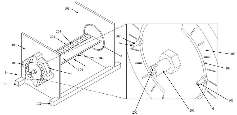
[0030] The piezoelectric energy harvesting test device for flow-induced vibration of a thin film wing of the present invention comprises a support 1, a wing connecting turntable 2, a thin film wing 3 and a piezoelectric sheet 4, such as figure 1 shown.

[0031] The support 1 is used to support the membrane wing 3, and has left and right baffles 101, two bottom beams 102 and a dial 103 installed on the left and right baffles 101 along the left and right directions. Among them, the left and right baffles 101 are rectangular plates with round holes in the center, perpendicular to the two bottom beams 102 , arranged near the two ends of the two bottom beams 102 , and the bottom edges are fixed to the two bottom beams 102 . The film wings 3 are arranged between the inner surfaces of the left and right baffles 101 . The dial 103 is a disc, which is fixed ...


PUM


Abstract

The invention discloses a flow-induced vibration piezoelectric energy collection test device of a film wing, belonging to the technical field of aeroelastic energy collection, comprising a support, a film wing and a piezoelectric sheet; The wing is connected to the turntable to install the membrane wing, and the membrane wing is driven by the rotating shaft plate to realize the adjustable angle of attack. The film wing includes front and rear edge shafts, front metal film and rear rubber film, and piezoelectric sheets are connected in series on the metal film; when adjusting the angle of attack of the film wing: first, adjust the angle of attack of the film wing; adjust to the test It needs to be fixed after the angle of attack; then, the rubber film is rolled up by rotating the trailing edge shaft to apply the required stress. Finally, under the action of the airflow, the film wing produces flow-induced vibration, and the piezoelectric sheet converts the strain energy into electrical energy. The invention can effectively prolong the service life of the piezoelectric sheet; and at the same time ensure that the aerodynamic performance of the thin-film airfoil is not affected, energy collection in different environments can be realized, and the energy conversion efficiency can be ensured.

Description

technical field [0001] The invention relates to a piezoelectric energy collection test device, in particular to a film wing flow-induced vibration piezoelectric energy collection test device, which belongs to the technical field of aeroelastic energy collection. Background technique [0002] Due to the small geometric size and low flight speed of micro-fixed-wing aircraft, its flying Reynolds number belongs to low Reynolds number flow, resulting in a significant decrease in its aerodynamic performance. At the same time, it is prone to stall when encountering gusts of wind, which affects its longitudinal stability. In addition, due to the low load capacity of the micro-aircraft, it is difficult to make a breakthrough in the energy density of the battery in a short time, so that the flight time and flight distance of the micro-aircraft are greatly limited. [0003] The film wing utilizes the great flexibility of the film, and the film vibrates under the action of the airflow,...

Claims


Application Information

Patent Timeline
Patent Type & Authority Patents(China)
IPC IPC(8): G01M9/00G01R31/00H02N2/18
CPCG01M9/00G01R31/008H02N2/185
Inventor 戴玉婷黄广靖杨超
Owner BEIHANG UNIV
Why Eureka
Try Eureka