
Wing-borne low-scattering ultra-wideband conformal phased array based on strong coupling effect

A strong-coupling, ultra-wideband technology, applied to phased antenna arrays with ultra-wide bandwidth angular scanning, and the field of flight carrier platforms, can solve the analysis and comparison of scattering characteristics of conformal phased arrays, and does not reflect phased arrays and frustum carriers Small curvature and other issues, to achieve the effect of improving ultra-wide bandwidth angular scanning characteristics, improving electric field distribution, and improving stealth performance

Active Publication Date: 2020-02-21
UNIV OF ELECTRONICS SCI & TECH OF CHINA
View PDF4 Cites 1 Cited by
  • Summary
  • Abstract
  • Description
  • Claims
  • Application Information

AI Technical Summary

Problems solved by technology

Its antenna unit adopts a strong coupling ultra-wideband planar antenna array unit, which has not been redesigned in a conformal environment. The curvature of the conformal frustum carrier of the entire phased array antenna is small, and the scattering of the conformal phased array is not considered. The analysis and comparison of the characteristics did not reflect the low scattering characteristics of the phased array conformal on the complex carrier platform

Method used


Image

  • Wing-borne low-scattering ultra-wideband conformal phased array based on strong coupling effect
  • Wing-borne low-scattering ultra-wideband conformal phased array based on strong coupling effect
  • Wing-borne low-scattering ultra-wideband conformal phased array based on strong coupling effect

Examples


Embodiment Construction

[0022] specific implementation plan

[0023] In order to make the object, technical solution and advantages of the present invention more clear, the present invention will be further described in detail in conjunction with the following specific examples.

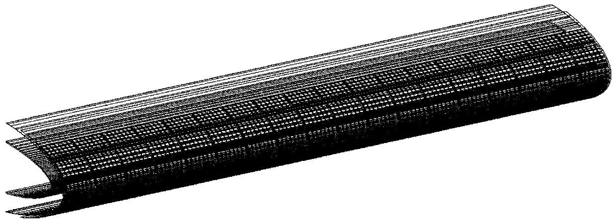
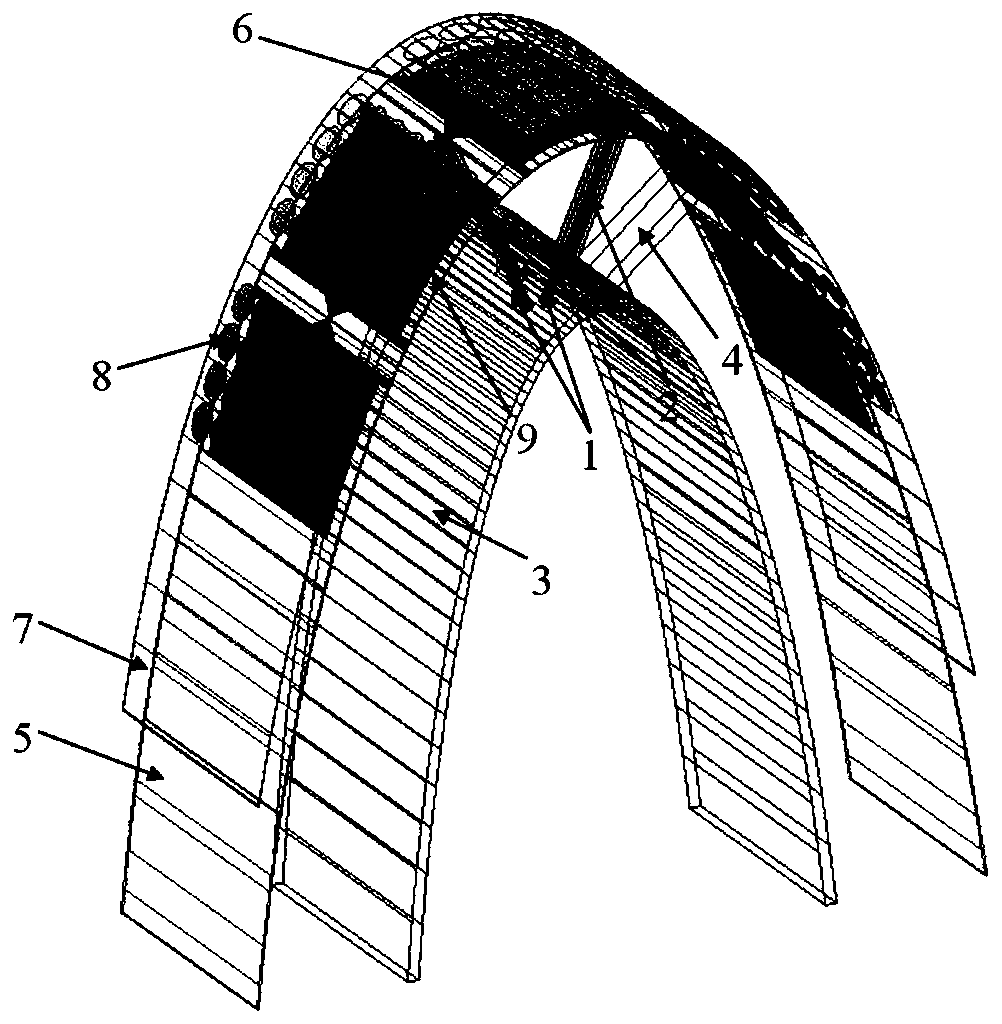
[0024]refer to Figure 1 to Figure 2 , the embodiment of the present invention consists of a layer of periodic structures printed with conformal long slot units, and uses one-dimensional periodic boundary conditions to simulate the simulation of the present invention in an infinite array environment. The antenna unit structure of the present invention is described as follows: the coaxial feed structure (1) of the antenna radiation unit; the gradient line balun (2) used to connect the antenna radiation patch and the feed structure; the metal floor conformal to the flight carrier (3); the parasitic metal block on the metal floor to simulate the loading of the ridge waveguide (4); the conformal dielectric substrate supporting...


PUM


Abstract

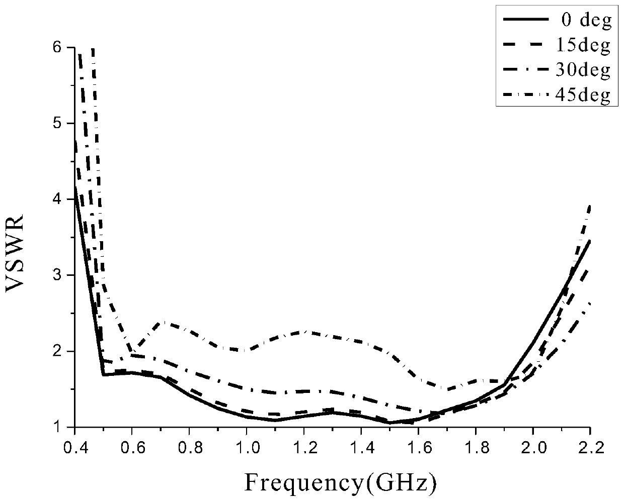
The invention discloses a wing-borne low-scattering ultra-broadband conformal phased array based on the strong coupling effect. The entire antenna structure of the array has been subjected to conformal processing, and it realizes the formation direction in the wide frequency band of 0.5-2GHz Compared with the traditional planar ultra-wideband phased array, the ±45°scan has significantly low scattering characteristics inside and outside the working frequency band of the antenna. The whole antenna structure mainly includes: the coaxial feed structure of the antenna radiation unit; the gradient line balun used to connect the antenna radiation patch and the feed structure; the metal floor conformal to the flight carrier; the parasitic metal block on the metal floor ; conformal dielectric substrate used to support the entire phased array antenna radiation structure; connected long slot conformal radiation patch based on strong coupling effect; conformal dielectric substrate used to support resistive electromagnetic metamaterials; with ultra-wideband electromagnetic wave absorption Circular resistive electromagnetic metamaterial for wave action; parasitic slots on both sides of antenna radiating element.

Description

technical field [0001] The invention belongs to the technical field of antenna engineering, and in particular relates to an ultra-wide bandwidth angular scanning conformal phased antenna array system, specifically an ultra-wide-bandwidth angular scanning conformal phased antenna array system based on a strong coupling effect, conformal to a local wing carrier platform, and having low scattering characteristics. Phased antenna array with wide bandwidth angular scan. It is especially suitable for flight carrier platforms that require antennas with good stealth performance and low profile characteristics, and can realize ultra-wide bandwidth angular scanning. Background technique [0002] With the increasing development of modern electronic information technology, especially the increasingly stringent requirements of military electronics on antenna performance, traditional mechanical scanning antennas have been difficult to meet the demand. Because the electronically scanned p...

Claims


Application Information

Patent Timeline
Patent Type & Authority Patents(China)
IPC IPC(8): H01Q1/28H01Q1/38H01Q1/48H01Q1/50H01Q9/16H01Q15/00H01Q17/00H01Q21/00H01Q21/08
CPCH01Q1/285H01Q1/287H01Q1/38H01Q1/48H01Q1/50H01Q9/16H01Q15/0086H01Q17/00H01Q21/0006H01Q21/08
Inventor 杨仕文郭星远王炳均陈益凯屈世伟胡俊黄明王立乔文昇
Owner UNIV OF ELECTRONICS SCI & TECH OF CHINA
Learn More