Flexible antenna array based on microwave energy transmission

A technology for flexible antennas and microwave energy transmission, which is applied in the directions of antenna arrays, individually powered antenna arrays, antennas, etc. performance, high-gain effects

Active Publication Date: 2021-06-25
CHONGQING UNIV
View PDF6 Cites 3 Cited by
  • Summary
  • Abstract
  • Description
  • Claims
  • Application Information

AI Technical Summary

Problems solved by technology

[0004] Aiming at the above-mentioned deficiencies in the prior art, a flexible antenna array based on microwave energy transmission provided by the present inv

Method used


Image

  • Flexible antenna array based on microwave energy transmission
  • Flexible antenna array based on microwave energy transmission
  • Flexible antenna array based on microwave energy transmission

Examples


Embodiment

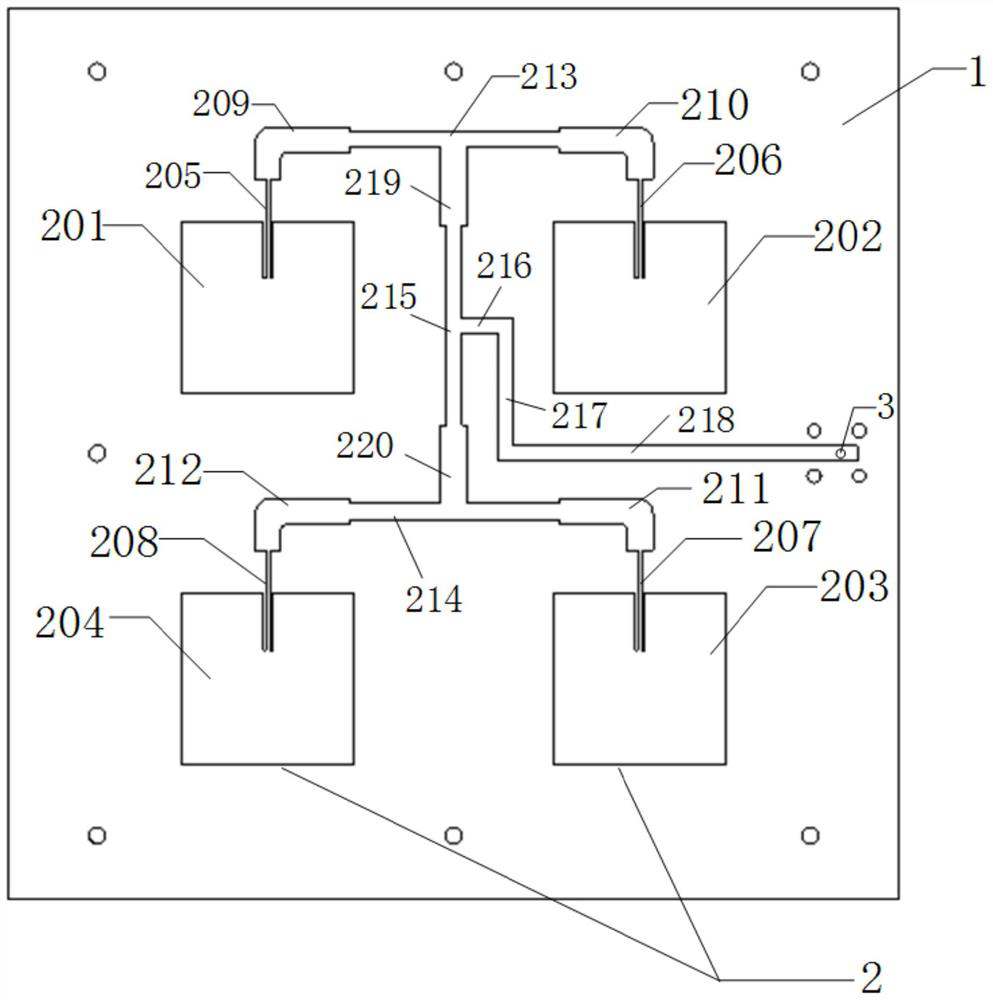
[0045] like figure 1 As shown, a flexible antenna array based on microwave energy transmission includes: a dielectric substrate 1, a patch array 2 and an equivalent ground plane layer 4;

[0046] One side of the dielectric substrate 1 is fixedly connected with the patch array 2 , and the other side thereof is fixedly connected with the equivalent ground plane layer 4 .

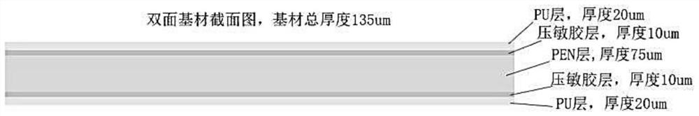
[0047] The dielectric substrate 1 includes a first PU layer, a first pressure-sensitive adhesive layer, a PEN layer, a second pressure-sensitive adhesive layer, and a second PU layer that are fixedly connected in sequence;

[0048] The thickness of the first PU layer is 20um; the thickness of the first pressure-sensitive adhesive layer is 10um; the thickness of the PEN layer is 75um; the thickness of the second pressure-sensitive adhesive layer is 10um; The thickness of the PU layer is 20um.

[0049] like figure 2 As shown, the dielectric substrate 1 is formed by laminating the first PU layer, the first pr...


PUM

PropertyMeasurementUnit
Thicknessaaaaaaaaaa
Thicknessaaaaaaaaaa
Thicknessaaaaaaaaaa

Abstract

The invention discloses a flexible antenna array based on microwave energy transmission. The flexible antenna array comprises a dielectric substrate, a patch array and an equivalent grounding plate layer. One surface of the dielectric substrate is fixedly connected with the patch array, and the other surface of the dielectric substrate is fixedly connected with the equivalent grounding plate layer. A liquid metal antenna which works at 2.45 GHZ and is used for microwave energy transmission is printed by applying a liquid metal printing technology and a flexible material. The liquid metal patch antenna gives full play to the advantages of repairability, flexibility, reconfigurability, fatigue resistance, corrosion resistance and the like of the liquid gallium indium metal and the flexible dielectric substrate, is applied to integrated small-sized electronic equipment, realizes receiving and transmitting of electromagnetic waves, is applied to long-distance energy wireless transmission, and overcomes the disadvantage of low unit energy collection and conversion efficiency of a traditional antenna.

Description

technical field [0001] The invention relates to the field of antennas, in particular to a flexible antenna array based on microwave energy transmission. Background technique [0002] The microwave receiving antenna and rectifier circuit are important components of the microwave energy transmission system, especially as the receiving end, with high energy collection and conversion efficiency, convenient and fast laying method, easy to conform to the structure of the load equipment, and have a certain self-healing ability. The new receiving antenna has important value for the promotion and application of microwave energy transmission. Compared with the traditional reflector antenna and planar array antenna, it has stronger flexibility and is an inevitable development trend in the future. [0003] Although the existing traditional patch antennas are small in size, there are problems that the antenna device is difficult to conform to and cannot maintain stable performance after ...

Claims


Application Information

Patent Timeline
IPC IPC(8): H01Q21/06H01Q1/00H01Q1/10H01Q1/36
CPCH01Q21/065H01Q1/002H01Q1/10H01Q1/364
Inventor 彭文雄明若彤郭思为李鑫源罗思怡张淮清陈远洋冯贞晶
Owner CHONGQING UNIV
Why Eureka
Try Eureka