Optical system, camera module and electronic device

A technology of optical system and camera module, applied in optics, optical components, instruments, etc.

Pending Publication Date: 2021-07-16
JIANGXI JINGCHAO OPTICAL CO LTD
View PDF0 Cites 2 Cited by
  • Summary
  • Abstract
  • Description
  • Claims
  • Application Information

AI Technical Summary

Problems solved by technology

[0003] Based on this, it is necessary to provide an optical system, camera module and electronic device for the problem of how to realize the small head design of the lens.

Method used


Image

  • Optical system, camera module and electronic device
  • Optical system, camera module and electronic device
  • Optical system, camera module and electronic device

Examples


no. 1 example

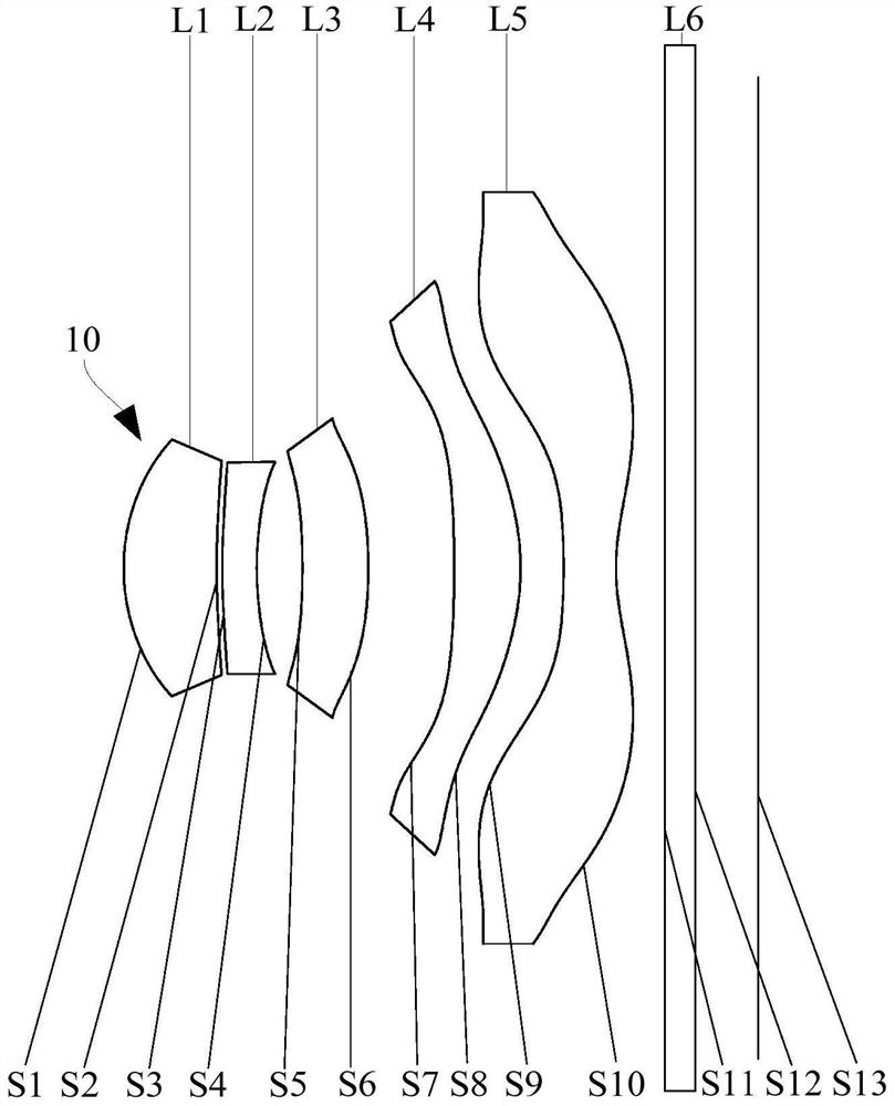
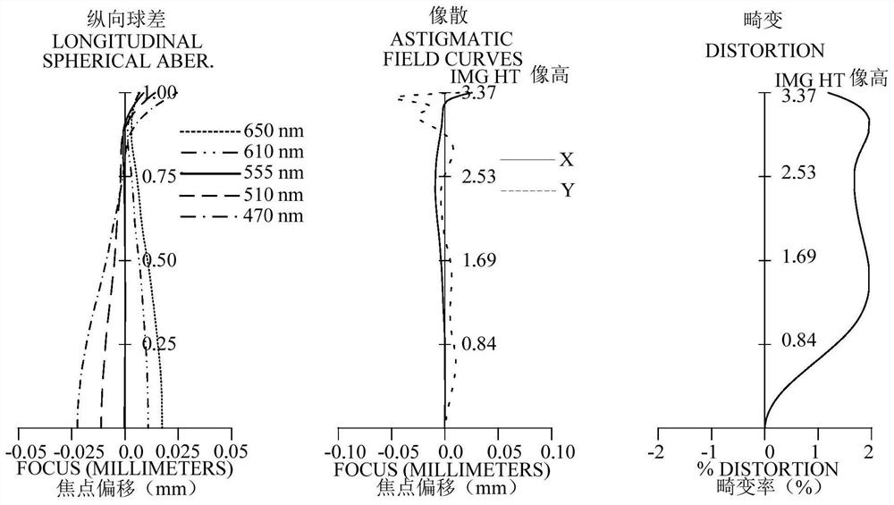
[0093] refer to figure 1 and figure 2 , in the first embodiment, the optical system 10 sequentially includes a first lens L1 with positive refractive power, a diaphragm arranged on the image side S2, a second lens L2 with negative refractive power, and a second lens L2 with negative refractive power from the object side to the image side. The third lens L3 with positive refractive power, the fourth lens L4 with positive refractive power, and the fifth lens L5 with negative refractive power. figure 2 It includes the longitudinal spherical aberration diagram (mm), astigmatism diagram (mm) and distortion diagram (%) of the optical system 10 in the first embodiment, wherein the astigmatism diagram and distortion diagram are graphs at a wavelength of 555nm.

[0094] The object side S1 of the first lens L1 is convex at the optical axis, and the image side S2 is concave at the optical axis; the object side S1 is convex at the circumference, and the image side S2 is concave at the ...

no. 2 example

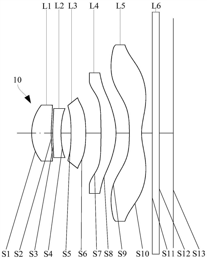
[0122] refer to image 3 and Figure 4 , in the second embodiment, the optical system 10 sequentially includes a first lens L1 with positive refractive power, a diaphragm, a second lens L2 with negative refractive power, and a third lens with positive refractive power from the object side to the image side L3, a fourth lens L4 with positive refractive power, and a fifth lens L5 with negative refractive power. Figure 4 It includes the longitudinal spherical aberration diagram (mm), astigmatism diagram (mm) and distortion diagram (%) of the optical system 10 in the second embodiment, wherein the astigmatism diagram and distortion diagram are graphs at a wavelength of 555nm.

[0123] Wherein, the ordinate of the astigmatism diagram and the distortion diagram can be understood as half of the diagonal length of the effective pixel area on the imaging plane S13 of the optical system 10 , and the unit of the ordinate is mm.

[0124] The object side S1 of the first lens L1 is conve...

no. 3 example

[0139] refer to Figure 5 and Image 6 , in the third embodiment, the optical system 10 sequentially includes a first lens L1 with positive refractive power, a diaphragm, a second lens L2 with negative refractive power, and a third lens with positive refractive power from the object side to the image side L3, a fourth lens L4 with positive refractive power, and a fifth lens L5 with negative refractive power. Image 6 It includes the longitudinal spherical aberration diagram (mm), astigmatism diagram (mm) and distortion diagram (%) of the optical system 10 in the third embodiment, wherein the astigmatism diagram and distortion diagram are graphs at a wavelength of 555 nm.

[0140] Wherein, the ordinate of the astigmatism diagram and the distortion diagram can be understood as half of the diagonal length of the effective pixel area on the imaging plane S13 of the optical system 10 , and the unit of the ordinate is mm.

[0141] The object side S1 of the first lens L1 is convex ...


PUM


Abstract

The invention relates to an optical system, a camera module and an electronic device. The optical system comprises, in order from an object side to an image side, a first lens with positive refractive power, a second lens with negative refractive power, a third lens with refractive power, a fourth lens with positive refractive power, and a fifth lens with negative refractive power, wherein the object side surface and the image side surface of the fifth lens are aspheric surfaces, and at least one of the object side surface and the image side surface of the fifth lens has an inflection point. The optical system comprises a diaphragm arranged on the image side of the first lens; the optical system satisfies the following relationship: 1.0 < SD11/tan (HFOV) + SAG11 < 1.5; and SD11 is the maximum effective radius of the object side surface of the first lens, HFOV is half of the maximum field angle of the optical system, and SAG11 is the rise of the object side surface of the first lens. The head of the optical system can be miniaturized by satisfying the relationship.

Description

technical field [0001] The invention relates to the field of optical imaging, in particular to an optical system, a camera module and an electronic device. Background technique [0002] In recent years, full-screen mobile phones have gradually become popular in the market, and how to achieve a higher screen-to-body ratio is the key to reducing the lens head. Although traditional camera lenses mounted on portable electronic products can meet miniaturization requirements, such as making the axial dimension smaller, the actual lens head is still relatively large, resulting in large screen openings, making it difficult to achieve a full screen design. Contents of the invention [0003] Based on this, it is necessary to provide an optical system, a camera module and an electronic device for the problem of how to realize the design of the small head of the lens. [0004] An optical system, sequentially comprising from the object side to the image side: [0005] a first lens h...

Claims


Application Information

Patent Timeline
Patent Type & Authority Applications(China)
IPC IPC(8): G02B13/00G02B13/18
CPCG02B13/0045G02B13/18
Inventor 邹金华李明刘彬彬邹海荣
Owner JIANGXI JINGCHAO OPTICAL CO LTD
Why Eureka
Try Eureka