Optical apparatus

A technology of optical devices and optical lenses, applied in optics, optical components, instruments, etc., can solve problems such as multi-space and overall volume reduction, achieve the effect of simplifying the number of components and improving the quality and effect of photography

Active Publication Date: 2016-05-11
EVERREADY PRECISION IND
View PDF3 Cites 1 Cited by
  • Summary
  • Abstract
  • Description
  • Claims
  • Application Information

AI Technical Summary

Problems solved by technology

However, the flashlight 7 occupies too much space, so it is difficult to effectively reduce the overall volume of the image capture device 8 equipped with the flashlight 7

Method used


Image

  • Optical apparatus
  • Optical apparatus
  • Optical apparatus

Examples


Embodiment Construction

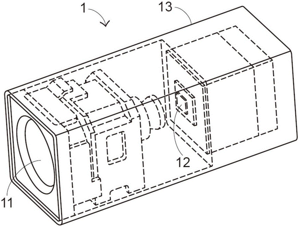
[0042] see Figure 5 and Figure 6 , Figure 5 It is a schematic diagram of the appearance structure of the optical device of the present invention in a first preferred embodiment, Figure 6 for Figure 5 A schematic partial cross-sectional view of the optical device shown along the line L-L. In this preferred embodiment, the optical device 3 is an optical camera device, and includes a first optical lens group 31, a second optical lens group 32, a third optical lens group 33, a fourth optical lens group 34, a light source assembly 35. Optical sensing element 36, optical filter 37, shading sheet 38, and used to house and fix the optical lens groups 31-34, light source assembly 35, optical sensing element 36, optical filter 37, and shading sheet 38 The shell 39. Wherein, the first optical lens group 31 includes the first lens 311, the third lens 312 and the fifth lens 313 in sequence along the direction of the first optical axis 314, and the third optical lens group 33 alon...


PUM


Abstract

An optical apparatus includes plural optical lens groups, an optical sensor, at least one lighting member and a casing. After a light beam passes through any of the plural optical lens groups, a travelling direction of the light beam is changed. After the light beam passes through at least one of the plural optical lens groups, the light beam is sensed and converted into an image signal by the optical sensor. The lighting member outputs a source beam. The plural optical lens groups, the optical sensor and the lighting member are accommodated within the casing. The optical apparatus has a single optical lens module, and is able to implement different optical functions simultaneously. Consequently, the overall volume of the optical apparatus is minimized, the fabricating cost of the optical apparatus is reduced, the assembling process is simplified, and the number of components to be assembled is reduced. Moreover, the camera shooting effects of the optical apparatus can be promoted.

Description

technical field [0001] The present invention relates to an optical device, in particular to an optical camera device with illumination function. Background technique [0002] see figure 1 , which is a schematic structural diagram of an existing single image photographing device. The single image photographing device 1 includes an optical lens 11, an image sensing element 12, and a housing 13, and the optical lens 11 is composed of at least one lens, and is used for allowing external light beams to pass therethrough, while the image sensing element 12 is used for The light beam passing through the optical lens 11 and incident on it is sensed, and then converted into an image signal for displaying images on the display, and the housing 13 is used to accommodate the optical lens 11 and the image sensing element 12, and provide a stable The positioning effect enables the optical lens 11 and the image sensor 12 to work normally. Among them, although figure 1 Shown is an indep...

Claims


Application Information

Patent Timeline
Patent Type & Authority Applications(China)
IPC IPC(8): G02B15/04G03B15/02G02B7/00G02B7/02G03B17/12G03B30/00
Inventor 陈志隆颜智敏
Owner EVERREADY PRECISION IND
Why Eureka
Try Eureka