Optical system, camera module and electronic equipment

An optical system and optical axis technology, applied in optics, optical components, instruments, etc., can solve problems such as image quality degradation, low resolution, and poor lens image quality, and achieve good camera quality, small footprint, and reduced obstacles Effect

Active Publication Date: 2022-05-27
JIANGXI JINGCHAO OPTICAL CO LTD
View PDF7 Cites 1 Cited by
  • Summary
  • Abstract
  • Description
  • Claims
  • Application Information

AI Technical Summary

Problems solved by technology

However, the increase in the number of lenses will increase the difficulty of lens design, processing and assembly, and the camera module with multi-chip design is often a large-scale structure in electronic equipment, which increases the volume of the lens; while the traditional compression method (Such as reducing the number of lenses) Although the size of the camera module can be shortened, it often leads to a decrease in image quality. The device maintains good imaging quality during the miniaturization design process, which is difficult to meet consumers' high-definition imaging needs for lenses

Method used


Image

  • Optical system, camera module and electronic equipment
  • Optical system, camera module and electronic equipment
  • Optical system, camera module and electronic equipment

Examples


no. 1 example

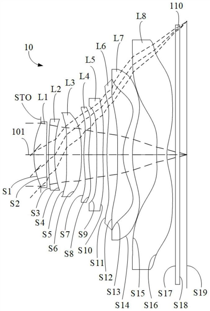
[0122] refer to figure 1 , in the first embodiment, the optical system 10 includes an aperture stop STO, a first lens L1 with positive refractive power, a second lens L2 with negative refractive power, and a second lens L2 with positive refractive power along the optical axis 101 from the object side to the image side. The third lens L3 with refractive power, the fourth lens L4 with negative refractive power, the fifth lens L5 with negative refractive power, the sixth lens L6 with positive refractive power, the seventh lens L7 with positive refractive power, and the seventh lens L7 with negative refractive power. Refractive power of the eighth lens L8. Each lens surface type of optical system 10 is as follows:

[0123] The object side S1 of the first lens L1 is a convex surface at the near optical axis 101, and the image side S2 is concave at the near optical axis 101;

[0124] The object side S3 of the second lens L2 is a convex surface at the near optical axis 101, and the...

no. 2 example

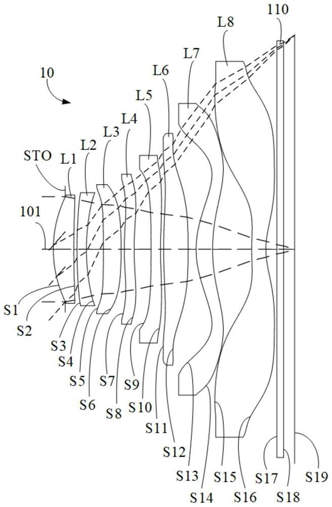
[0152] refer to image 3 , in the second embodiment, the optical system 10 includes an aperture stop STO, a first lens L1 with positive refractive power, a second lens L2 with negative refractive power, and a second lens L2 with positive refractive power along the optical axis 101 from the object side to the image side. The third lens L3 with refractive power, the fourth lens L4 with positive refractive power, the fifth lens L5 with negative refractive power, the sixth lens L6 with positive refractive power, the seventh lens L7 with positive refractive power, and the seventh lens L7 with negative refractive power. Refractive power of the eighth lens L8. Each lens surface type of optical system 10 is as follows:

[0153] The object side S1 of the first lens L1 is a convex surface at the near optical axis 101, and the image side S2 is concave at the near optical axis 101;

[0154] The object side S3 of the second lens L2 is a convex surface at the near optical axis 101, and th...

no. 3 example

[0169] refer to Figure 5 , in the third embodiment, the optical system 10 includes an aperture stop STO, a first lens L1 with positive refractive power, a second lens L2 with negative refractive power, and a second lens L2 with positive refractive power along the optical axis 101 from the object side to the image side. The third lens L3 with refractive power, the fourth lens L4 with negative refractive power, the fifth lens L5 with negative refractive power, the sixth lens L6 with negative refractive power, the seventh lens L7 with positive refractive power, and the seventh lens L7 with negative refractive power. Refractive power of the eighth lens L8. Each lens surface type of optical system 10 is as follows:

[0170] The object side S1 of the first lens L1 is a convex surface at the near optical axis 101, and the image side S2 is concave at the near optical axis 101;

[0171] The object side S3 of the second lens L2 is a convex surface at the near optical axis 101, and th...


PUM


Abstract

The invention discloses an optical system, a camera module and electronic equipment. The optical system includes: a first lens having positive refractive power; a second lens element with negative refractive power; a third lens element with positive refractive power, the image-side surface of the third lens element being convex in a paraxial region; a fourth lens element with refractive power; the fifth lens element with negative refractive power has an image-side surface being concave in a paraxial region thereof. A sixth lens element with refractive power; a seventh lens element with positive refractive power; an eighth lens element with negative refractive power, wherein the image-side surface of the eighth lens element near the optical axis is a concave surface; the object side surfaces and the image side surfaces of the first lens, the second lens, the fourth lens and the seventh lens are convex surfaces and concave surfaces at positions near the optical axis respectively; the optical system satisfies the relationship: 1.2 < = TTL/Imgh < = 1.3. According to the optical system provided by the embodiment of the invention, good imaging quality can be taken into account while light, thin and miniaturized design is realized.

Description

technical field [0001] The invention relates to the technical field of photography and imaging, in particular to an optical system, a camera module and electronic equipment. Background technique [0002] With the development of camera technology, the market demand for portable electronic devices such as smartphones, smart watches, and smart glasses has increased significantly, and consumers have higher and higher requirements for the imaging quality and functions of lenses. Not only do they require lenses to be thinner and smaller, At the same time, a higher image quality should be achieved. The lens can obtain image information and is the main module of electronic equipment to realize image capture. With the rapid improvement of people's living standards and the rapid development of science and technology, the pixel size of the image sensor closely matched with the lens is continuously reduced, which requires the lens to achieve higher quality imaging effects. [0003] At...

Claims


Application Information

Patent Timeline
Patent Type & Authority Applications(China)
IPC IPC(8): G02B13/00G02B13/18
CPCG02B13/0015G02B13/0045G03B30/00
Inventor 曾晗李明
Owner JIANGXI JINGCHAO OPTICAL CO LTD
Why Eureka
Try Eureka