Camera module

一种照相机、小型的技术,应用在照相机、照相机的机身、仪器等方向,能够解决很难定位透镜和固体摄像器件、硅片切割不均匀等问题,达到摄像质量高、定位精度高的效果

Active Publication Date: 2012-11-21
MAXELL HLDG LTD
View PDF6 Cites 1 Cited by
  • Summary
  • Abstract
  • Description
  • Claims
  • Application Information

AI Technical Summary

Problems solved by technology

However, in this case, it is difficult to position the lens and solid-state imaging device with high precision due to uneven adhesive or uneven dicing of the silicon wafer

Method used


Image

  • Camera module
  • Camera module
  • Camera module

Examples


Embodiment approach 1

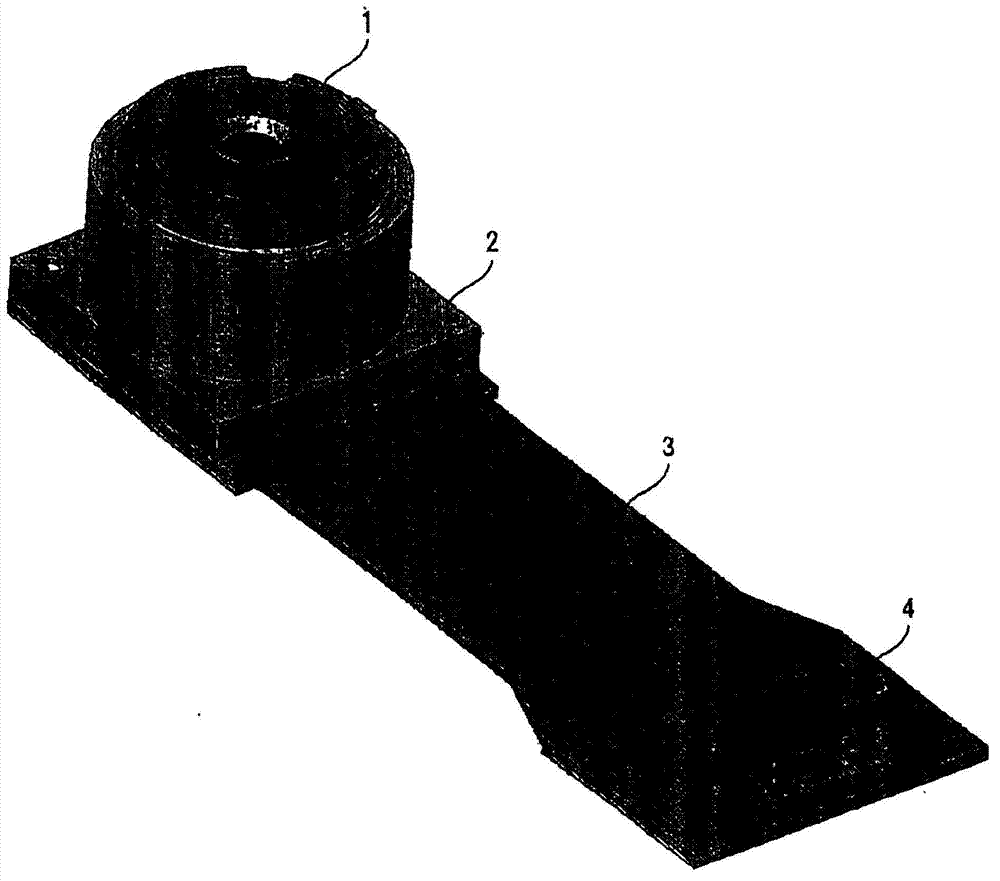
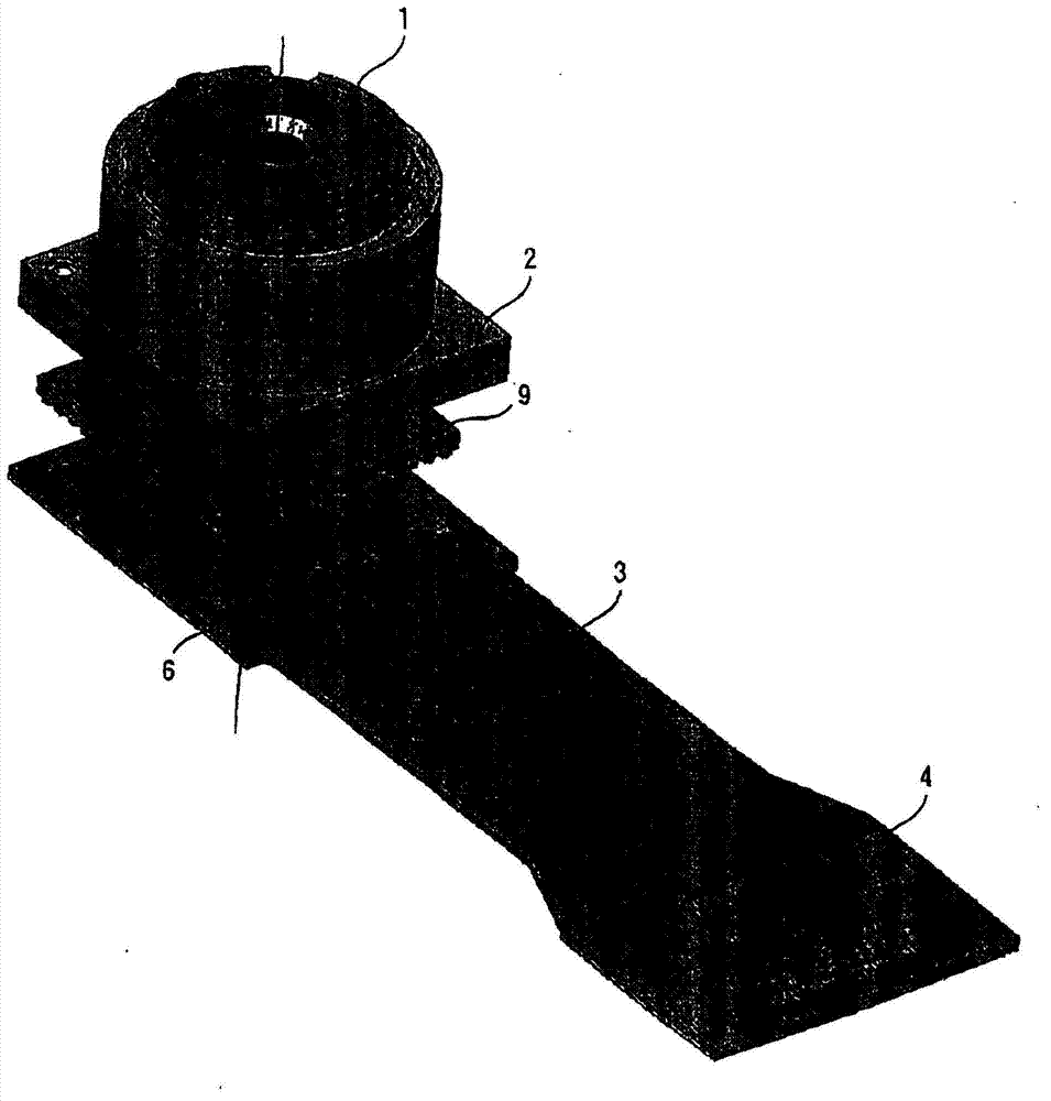
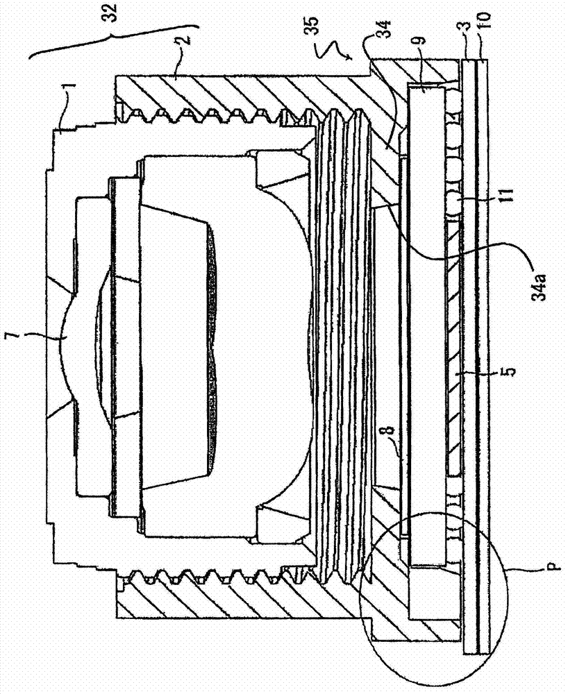
[0039] figure 1 It is a perspective view of the camera module of this invention. figure 2 It is an exploded perspective view of the camera module. in addition, image 3 is a cross-sectional view of the camera module.

[0040] Such as Figure 1~3 As shown, the camera module of the present invention has: lens module 1; Base 2; FPC circuit board 3; Connector 4; Solid-state imaging device 5; Capacitor 6; Lens 7; 10; and solder balls 11.

[0041] The lens module 1 has a cylindrical shape, and one or more lenses 7 are fixed to its inner peripheral surface with high precision. In addition to the lens 7 , an aperture or an O-ring may sometimes be provided on the lens module 1 . A cutting thread structure is provided on the outer peripheral surface of the lens module 1 so as to be screwed on the base 2 . The lens module 1 is made of, for example, a light-shielding synthetic resin such as black polycarbonate or polybutylene terephthalate.

[0042]The base 2 has a cylindrical sh...

Embodiment 1

[0093] The thickness of the lens holder 32 of the camera module of Example 1 was manufactured according to the following conditions. Furthermore, the composition of the camera module, and Figure 9The configuration shown is the same.

[0094] S∕(H×H)=0.1

Embodiment 2

[0096] The thickness of the lens holder 32 of the camera module of Example 2 was manufactured according to the following conditions. Furthermore, the composition of the camera module, and Figure 9 The configuration shown is the same.

[0097] S∕(H×H)=0.2


PUM


Abstract

A camera module includes a mount for holding a lens directly or indirectly, a cover plate glass with transparency fixed to the mount. A solid-state imaging device is mounted on the cover plate glass. The cover plate contacts a plurality of ribs formed in the mount, and the mount and the cover plate are positioned.

Description

[0001] This application is a divisional application of the patent application submitted on February 1, 2007, with the application number 200710006504.4 and the title of the invention "camera module". technical field [0002] The present invention relates to camera modules. Background technique [0003] A camera module including a lens and a solid-state imaging device is mounted on various devices such as mobile phones. In a camera module, a solid-state imaging device is directly or indirectly fixed on a base. The imaging quality of a camera module greatly changes depending on the relative positions of the solid-state imaging device and the lens. Therefore, it is particularly important to correctly position the solid-state imaging device and the lens. [0004] Patent Document 1 (Japanese Unexamined Patent Publication No. 2005-347397 ) discloses a configuration example of a camera module. In the camera disclosed in this document, a solid-state imaging device is formed on a ...

Claims


Application Information

Patent Timeline
Patent Type & Authority Applications(China)
IPC IPC(8): H04N5/225G03B17/12G03B30/00
CPCH04N5/2254G03B17/02H04N5/2257H04N5/2253H04N23/54H04N23/55H04N23/57H04N23/00
Inventor 青木进麿毅
Owner MAXELL HLDG LTD
Why Eureka
Try Eureka