
Novel stop valve
A globe valve, a new type of technology, applied in the directions of lift valves, valve details, valve devices, etc., can solve the problems of inconvenient disassembly and assembly of globe valves, high cost, save maintenance time, reduce procurement costs, and reduce manufacturing costs.
- Summary
- Abstract
- Description
- Claims
- Application Information
AI Technical Summary
Problems solved by technology
Method used
Image

Examples
specific Embodiment approach 1
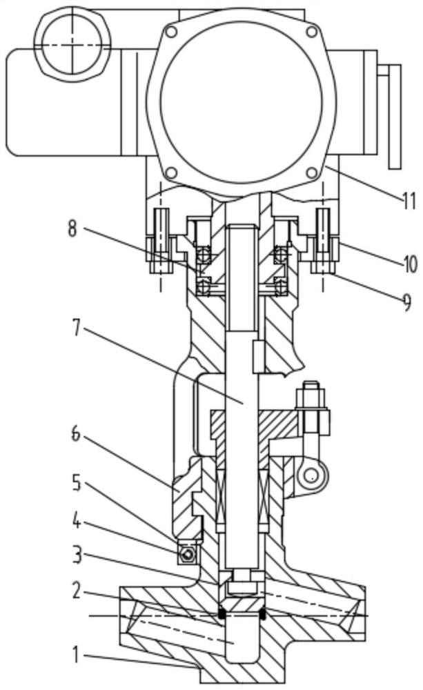
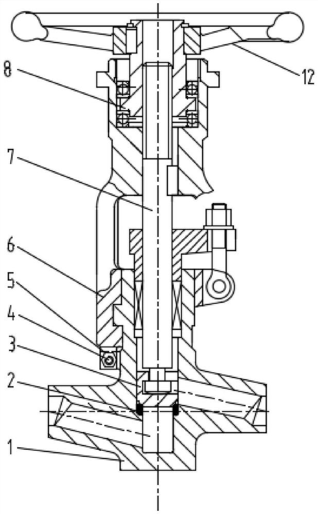
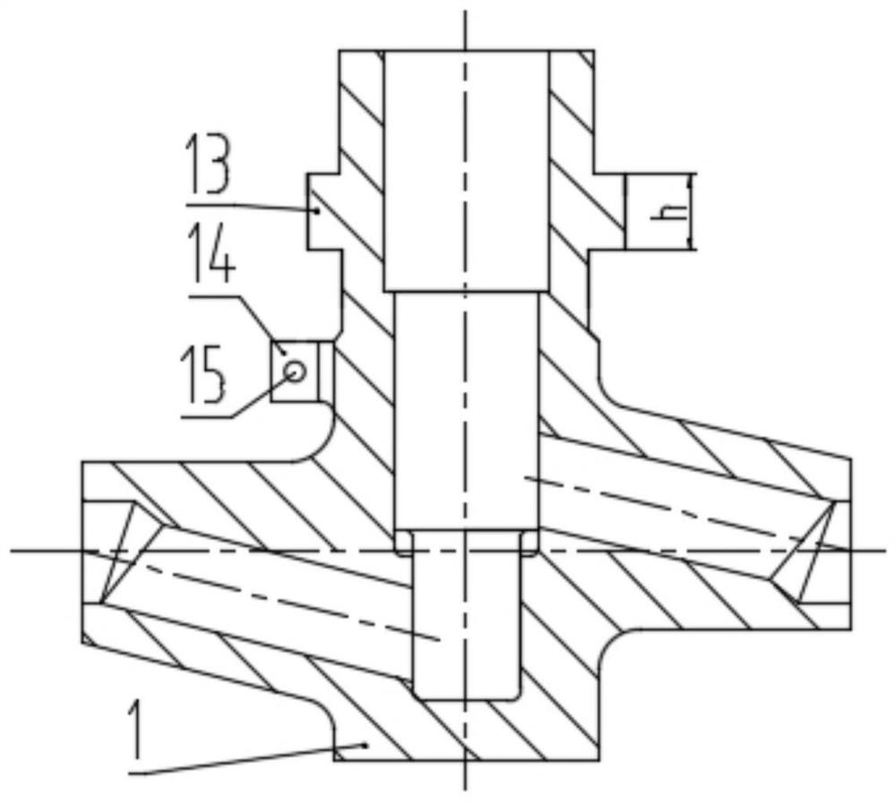
[0032] Specific implementation mode one: combine Figure 1-Figure 7 Describe this embodiment, a new shut-off valve of this embodiment, including valve body 1, valve seat 2, valve flap 3, bracket 6, valve stem 7 and valve stem nut 8, valve body 1 is provided with valve seat 2, The valve disc 3 is installed in the inner cavity of the valve body 1, the valve disc 3 is connected with the valve stem 7, the valve disc 3 is arranged on the valve seat 2, the valve body 1 is connected with the bracket 6, and a pair of The first arc-shaped boss 13 is also provided with a first positioning platform 14 on the side wall of the valve body 1. The first positioning platform 14 is located below the first arc-shaped boss 13, and the inner wall of the lower part of the bracket 6 is provided with a first arc-shaped The arc ferrule 19 that the boss 13 matches, the first arc boss 13 is installed in the arc ferrule 19, the second positioning platform 17 is installed on the bottom end surface of the ...
specific Embodiment approach 2
[0033] Specific implementation mode two: combination Figure 1-Figure 8 Describe this embodiment, a new cut-off valve of this embodiment, also includes a flange 10 and an electric device 11, the flange 10 is connected to the support 6, and the electric device 11 is connected to the support 6 through the flange 10;
[0034] Specifically, a pair of second arc-shaped bosses 16 are symmetrically arranged on the upper side wall of the bracket 6, two buckles 20 matching the second arc-shaped bosses 16 are symmetrically arranged on the flange 10, and the second arc-shaped bosses 16 are symmetrically arranged. Shaped boss 16 is installed with buckle 20, and flange plate 10 enters below the second arc-shaped boss 16 of support 6 from the neutral position of second arc-shaped boss 16 of support 6, and flange plate 10 and support 6 Relatively rotate 90°, then lift up the flange plate 10, so that the buckle 20 of the flange plate 10 is under the second arc-shaped boss 16 of the bracket 6,...
specific Embodiment approach 3
[0036] Specific implementation mode three: combination Figure 1-Figure 8 Describe this embodiment, a new cut-off valve of this embodiment also includes a handwheel 12, the handwheel 12 is fixedly installed on the valve stem nut 9, the handwheel 12 is installed in cooperation with the valve stem nut 8, and is controlled by rotating the handwheel 12. The valve stem 7 drives the valve clack 3 to open or close.
PUM
 Abstract
Description
Claims
Application Information