An offshore wind generator with a speed reduction device

A technology for wind turbines and deceleration devices, applied in wind turbines, wind turbine combinations, wind turbine control, etc., can solve the problems of low intelligence and high energy consumption, etc.

Active Publication Date: 2022-05-06
李慧
View PDF19 Cites 0 Cited by
  • Summary
  • Abstract
  • Description
  • Claims
  • Application Information

AI Technical Summary

Problems solved by technology

[0005] The purpose of the present invention is to address the deficiencies of the prior art and provide an offshore wind generator with a speed reduction device. By setting a first Venturi device and a second Venturi device on the tower, the first Venturi device The device and the second Venturi device are equipped with slide pipes, sliders and deceleration components, and one end of the first Venturi device and the second Venturi device is provided with a windshield component and a push component, which solves the problem of strong winds encountered by offshore wind turbines. When using wind power to effectively reduce the speed of the generator, the energy consumption is large, and the intelligence level is low, etc.

Method used


Image

  • An offshore wind generator with a speed reduction device
  • An offshore wind generator with a speed reduction device
  • An offshore wind generator with a speed reduction device

Examples


Embodiment 1

[0034] The following describes in detail the embodiments of the present invention, examples of which are illustrated in the accompanying drawings, wherein the same or similar reference numerals refer to the same or similar elements or elements having the same or similar functions throughout. The embodiments described below with reference to the accompanying drawings are exemplary, and are intended to explain the present invention and should not be construed as limiting the present invention.

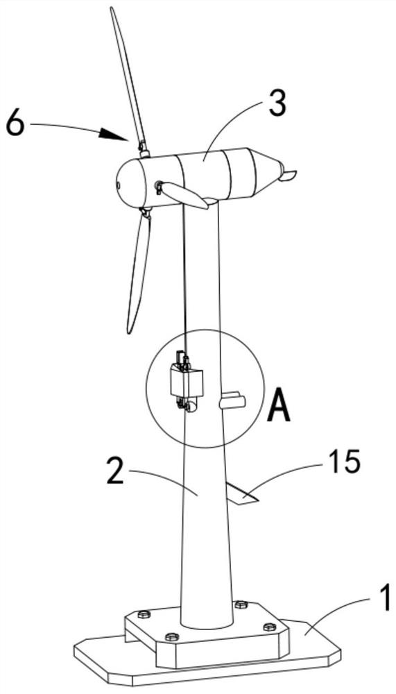
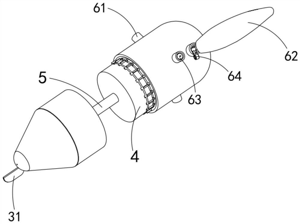
[0035] like Figure 1 to Figure 10 As shown, an offshore wind power generator with a speed reduction device includes a base 1, a tower 2 arranged on the base 1, a nacelle 3 arranged on the tower 2, a unit 4 arranged in the nacelle 3, and a Several swing assemblies 6 on one end of the rotating shaft 5 of the unit 4, the tower 2 is provided with a first Venturi device 7 and a second Venturi device 8, the first Venturi device 7 and the second Venturi device 8 8 all include a venturi 9, a s...

Embodiment 2

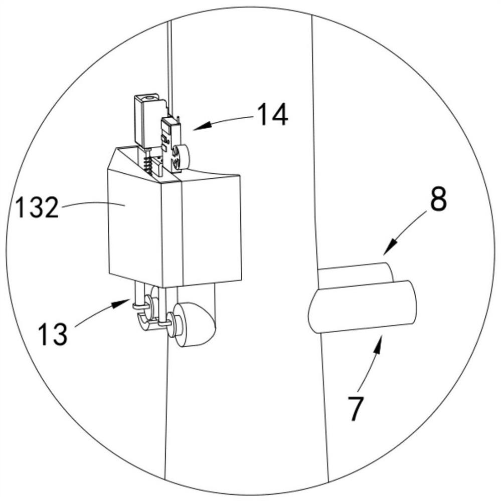
[0048] like Figure 4 As shown in the figure, the same or corresponding parts as in the first embodiment are marked with the corresponding reference numerals as in the first embodiment. For the sake of brevity, only the differences from the first embodiment are described below; the difference between the second embodiment and the first embodiment The point is that a convex block 81 is fixedly arranged at the air inlet 91 of the venturi tube 9 in the second venturi device 8 .

[0049] The bumps 81 provided in this embodiment are used to limit the position of the windshield b139 during the reset process, so that the windshield b139 is just at the air inlet 91 of the venturi tube 9 , which can effectively block the air inlet 91 The wind also prevents the wind deflector b139 from slipping.

[0050] work process


PUM


Abstract

The invention relates to an offshore wind power generator with a deceleration device, which includes a base, a tower, a nacelle, a unit and several swing assemblies arranged on one end of the rotating shaft of the unit, and a first and a second Venturi are arranged on the tower device, the first and second Venturi devices all include a Venturi tube, a slide tube, a slider and a deceleration assembly, and one end of the first and second Venturi devices is provided with a windshield assembly and a push assembly; the push assembly drives the windshield assembly in turn Open the air inlet of the Venturi tube in the first Venturi device and the second Venturi device, and form a negative pressure area at the slide tube, the slider moves up and down in the slide tube under the push of air pressure, and drives the deceleration assembly to decelerate the shaft The present invention solves the problems that current offshore wind power generators cannot use the wind force to effectively reduce the speed of the generator shaft when encountering strong winds, the energy consumption is relatively large, and the service life of the generator is short.

Description

technical field [0001] The invention relates to the technical field of wind energy industry, in particular to an offshore wind generator with a deceleration device. Background technique [0002] Under the increasingly severe situation of oil resources, all countries have turned their attention to sea areas with huge wind resources. As a clean energy, wind power itself has many advantages, such as being environmentally friendly, short in construction period, and low in operation and maintenance costs. The emerging offshore wind power is better than the onshore wind power, and the huge windmill fields have become a beautiful landscape. However, offshore generators also have the problem of damage to components due to too fast rotation speed when encountering strong winds, which is cumbersome in terms of maintenance. Therefore, a deceleration device is urgently needed to decelerate the generator and prolong the service life of the generator. [0003] A Chinese invention with pu...

Claims


Application Information

Patent Timeline
Patent Type & Authority Patents(China)
IPC IPC(8): F03D9/25F03D7/02F03D80/80F03D17/00F04F5/16
CPCF03D9/25F03D7/0248F03D7/024F03D80/88F03D17/00F04F5/16F05B2270/32F05B2240/95Y02E10/727Y02E10/72
Inventor 不公告发明人
Owner 李慧
Why Eureka
Try Eureka