Power supply system

A power supply system and battery technology, which is applied in the direction of circuits, electrical components, secondary batteries, etc., can solve the problems of expansion of loading space, expansion of loading power system space, and unoptimization, so as to improve the strength of the shell and suppress the loading space Extended effect

Pending Publication Date: 2021-12-17
TOYOTA IND CORP
View PDF9 Cites 0 Cited by
  • Summary
  • Abstract
  • Description
  • Claims
  • Application Information

AI Technical Summary

Problems solved by technology

However, if only the strength member is attached to the case, there is a concern that the case will increase in size and the space for placing the power supply system will increase.
In addition, since the power supply system is often arranged in a limited space, it is not preferable to expand the mounting space.

Method used


Image

  • Power supply system
  • Power supply system
  • Power supply system

Examples


Embodiment approach 1

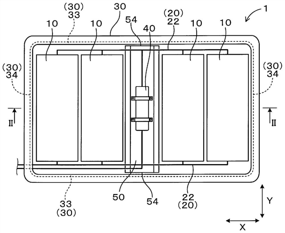
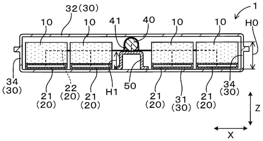
[0032] use Figure 1 ~ Figure 3 Embodiments of the power supply system described above will be described.

[0033] like figure 1 and figure 2 As shown, the power supply system 1 of the present embodiment includes a battery 10 , a cooling unit 20 , a case 30 , a compressor 40 , and a strength member 50 .

[0034] A plurality of batteries 10 are provided.

[0035] The cooling unit 20 circulates a refrigerant for cooling the plurality of batteries 10 .

[0036] The casing 30 has a bottom plate 31 , a top plate 32 , and side walls 33 and 34 standing upright from the outer peripheral edge of the bottom plate 31 to the outer peripheral edge of the top plate 32 . Furthermore, the casing 30 accommodates the plurality of batteries 10 and the cooling unit 20 inside.

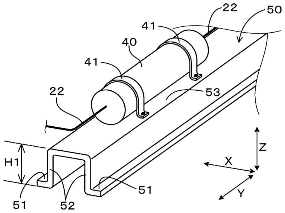
[0037] The compressor 40 pumps the refrigerant to the cooling unit 20 .

[0038] Inside the case 30 , a strength member 50 extending in the opposing direction of the mutually opposed side walls 33 and reinforcing th...


PUM


Abstract

The invention provides a power supply system in which while enlargement of a space for placement of the power supply system is suppressed, strength of a housing is improved. The power supply system (1) includes a plurality of batteries (10), a cooling portion (20) through which a refrigerant for cooling the plurality of the batteries flows, a housing (30) that has a bottom plate (31), a top plate (32), and side walls (33, 34) that extend upright from a peripheral edge of the bottom plate to a peripheral edge of the top plate, the housing accommodating the plurality of the batteries and the cooling portion, and a compressor configured to pump the refrigerant to the cooling portion. In the housing, a strength member that extends in a direction in which the side walls face each other and reinforces the housing is mounted on the bottom plate or the top plate. The compressor is disposed in a position in which the compressor and the strength member are overlapped in the upright direction of the side walls.

Description

technical field [0001] The present invention relates to power systems. Background technique [0002] Conventionally, a power supply system is used in which a plurality of batteries and a cooling mechanism for circulating a refrigerant for cooling the batteries are accommodated in a casing. For example, Patent Document 1 discloses a structure in which an evaporative cooling unit and a compressor for pumping refrigerant to the cooling unit are provided inside a casing, and a plurality of batteries are arranged on the cooling unit. In the above structure, the battery above the cooling member is cooled by the refrigerant pumped by the compressor, thereby suppressing the battery from becoming high temperature. [0003] Patent Document 1: Japanese Patent No. 6010212 [0004] On the other hand, when the power supply system receives an impact from the outside, there is a possibility that the internal battery and cooling components may be damaged. In particular, when a power suppl...

Claims


Application Information

Patent Timeline
Patent Type & Authority Applications(China)
IPC IPC(8): H01M50/202H01M50/236H01M10/613H01M10/66
CPCH01M50/202H01M50/236H01M10/613H01M10/66Y02E60/10H01M10/625H01M50/20H01M10/6568H01M10/6556H01M2220/20H01M10/647H01M50/209H01M10/6563H01M10/6557H05K7/20354H05K7/20327H01M10/6552
Inventor 松本裕介
Owner TOYOTA IND CORP
Why Eureka
Try Eureka