Anti-pulling type pipe pile and construction process thereof

A technology of anti-pull and pipe piles, which is applied in the direction of sheet pile walls, foundation structure engineering, construction, etc., and can solve the problems of easy corrosion of the welding joints of pipe pile connection end plates, reduced bearing capacity of pipe piles, insufficient pullout bearing capacity, etc. Problems, to achieve the effect of simple connection structure, improved pull-out bearing capacity, and good coaxiality

Active Publication Date: 2022-01-18
浙大宁波理工学院
View PDF9 Cites 2 Cited by
  • Summary
  • Abstract
  • Description
  • Claims
  • Application Information

AI Technical Summary

Problems solved by technology

At the same time, for piled raft foundations in basements with shallow groundwater levels, if pipe piles are used, they need to have a higher uplift bearing capacity. The existing traditional pipe piles have insufficient uplift bearing capacity, and the single pile has a low bearing capacity. It cannot meet the growing construction requirements, and in the process of pile connection, the welded end plate of the pipe pile is easily corroded, which also reduces the bearing capacity of the pipe pile

Method used


Image

  • Anti-pulling type pipe pile and construction process thereof
  • Anti-pulling type pipe pile and construction process thereof
  • Anti-pulling type pipe pile and construction process thereof

Examples


Embodiment 1

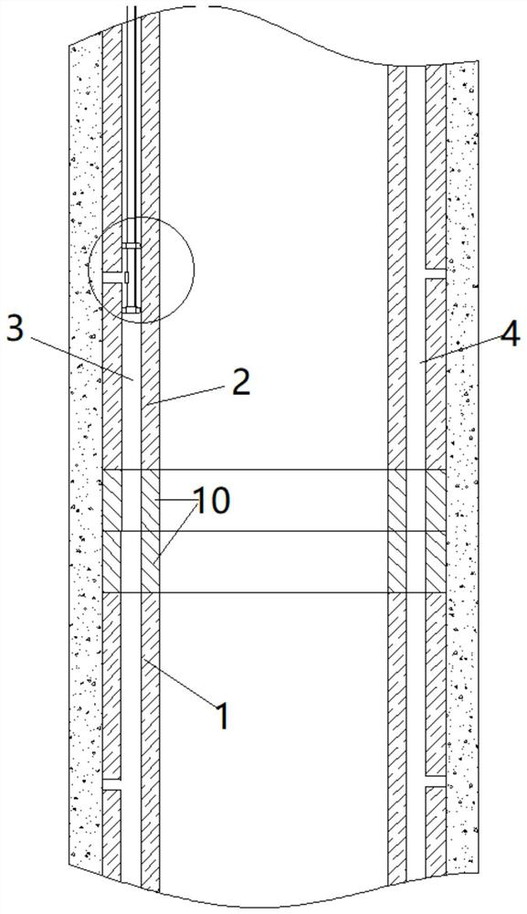
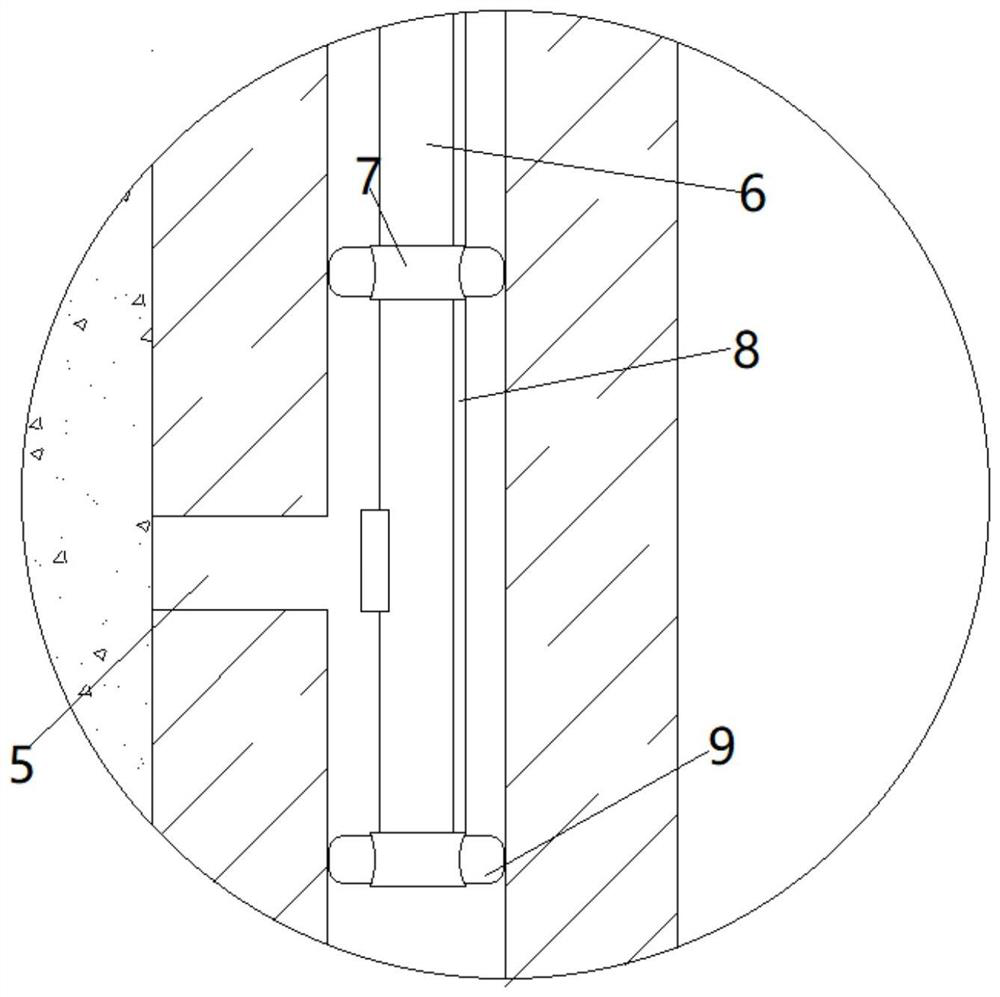
[0028] Such as Figure 1-6 As shown, the present invention discloses an anti-pull pipe pile, including a pipe pile, a connecting end plate 10 and a high-pressure grouting device. The inner cavity of the pile surrounded by the pile body is equipped with a reinforcement cage made of steel bars, and the two opposite side faces inside the pile body are respectively embedded with the first grouting pipe 3 and the second grouting pipe 4, the first grouting pipe 4 Both the grouting pipe 3 and the second grouting pipe 4 run through the entire pile body, and the outer wall of the pipe pile is provided with a number of grouting holes 5, the grouting holes 5 communicate with the first grouting pipe 3 and the second grouting pipe 4, and the surface of the pile body It is coated with silane paint, and after the silane paint is air-dried, it is coated with cement-based permeable crystalline waterproof paint to improve the durability of concrete. Two sets of grouting pipes are symmetrically ...

Embodiment 2

[0032] A construction technique for an anti-pull pipe pile, comprising:

[0033] a. According to the surrounding environment and soil conditions, choose the hammering method or the static pressure method for construction, check whether the high-pressure grouting pipe is blocked, and ensure that the high-pressure grouting pipe is unobstructed;

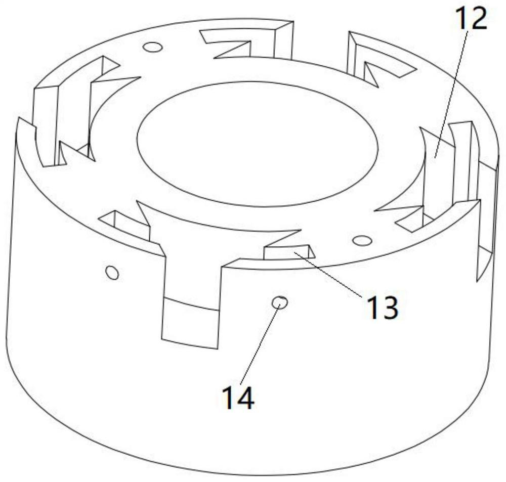
[0034] b. Press the lower pipe pile 1 into the soil layer by hammering method or static pressure method. When the upper end of the lower pipe pile 1 is 1m away from the surface of the soil layer, connect the upper and lower pipe piles through the connecting end plate 10, and place the upper pipe pile 2 The tenon 11 is inserted into the mortise 12 of the lower pipe pile 1, the latch is inserted into the joint end plate 10, and the connection end plate 10 is welded;

[0035] c. Carry out the pile delivery according to the design requirements, wait for the pipe pile to go deep into the designated position, extend the high-pressure grouting...


PUM


Abstract

The invention discloses an anti-pulling type pipe pile and a construction process thereof, and belongs to the technical field of concrete pipe piles. The anti-pulling type pipe pile comprises a pipe pile body, connecting end plates and a high-pressure grouting device, wherein the pipe pile body comprises a pile main body manufactured by adopting a pre-tensioning method pre-stress process and a centrifugal forming method, and a pile main body inner cavity defined by the pile main body; a steel reinforcement cage woven by steel bars is arranged in the pile main body inner cavity; a first grouting pipe and a second grouting pipe are embedded in the two opposite side end surfaces in the pile main body correspondingly and penetrate through the whole pile main body; a plurality of grouting holes are formed in the outer wall of the pipe pile body and communicate with the first grouting pipe and the second grouting pipe; the connecting end plates are arranged at the joints of an upper pipe pile and a lower pipe pile correspondingly and are of mortise and tenon structures; the high-pressure grouting device comprises a high-pressure grouting machine and a high-pressure grouting pipe; the high-pressure grouting pipe is arranged on the high-pressure grouting machine; and sealing devices are arranged at the two ends of a grout outlet of the high-pressure grouting pipe. According to the anti-pulling type pipe pile and the construction process thereof, local grouting of key positions can be realized, and the anti-pulling bearing capacity of the pipe pile can be improved.

Description

technical field [0001] The invention relates to the technical field of concrete pipe piles, in particular to a pullout-resistant pipe pile and a construction process thereof. Background technique [0002] With the development of the economy, the number of high-rise buildings in cities is increasing year by year. During the construction of high-rise buildings, when the geological structure with soft soil is encountered, the bearing capacity of the foundation is small, and the buildings are easy to sink. At this time, it is necessary to drive the pipe pile into the soil layer in advance. Among them, the side resistance and end resistance of pipe piles bear the upper load together, thereby improving the bearing capacity of the foundation. Especially in coastal soft soil areas, pipe piles are widely used in various engineering piles and foundation pit enclosure piles. With the expansion of the application field of pipe piles, the requirements for the application of pipe piles ar...

Claims


Application Information

Patent Timeline
Patent Type & Authority Applications(China)
IPC IPC(8): E02D5/52E02D5/58E02D5/62E02D15/04
CPCE02D5/52E02D5/526E02D5/58E02D5/62E02D15/04E02D2250/003E02D2600/20E02D2300/0014E02D2300/0001
Inventor 查支祥潘崇根任晶鸽王韬何建明彭卫董佳蓉
Owner 浙大宁波理工学院
Why Eureka
Try Eureka