Paste slurry drilling, grouting and impact extrusion expanded-head anchor rod structure system and construction method thereof

A construction method and head-enlarging technology, which are used in infrastructure engineering, soil protection, sheet pile walls, etc., can solve problems such as difficulty in ensuring the quality of anchoring, unclean hole cleaning for lower anchors, and difficulty in forming holes for wall protection. Creep amount, convenient construction, and the effect of improving mechanical properties

Pending Publication Date: 2020-11-10
POWERCHINA ZHONGNAN ENG +1
View PDF7 Cites 2 Cited by
  • Summary
  • Abstract
  • Description
  • Claims
  • Application Information

AI Technical Summary

Problems solved by technology

Due to the loose and weak geological characteristics of the soil layer structure, the existing enlarged head-type anchor structure system has many problems such as complicated construction procedures, difficulty in forming holes and retaining walls, unclean anchor cleaning holes, and difficulty in ensuring anchorage quality. technical problem

Method used


Image

  • Paste slurry drilling, grouting and impact extrusion expanded-head anchor rod structure system and construction method thereof
  • Paste slurry drilling, grouting and impact extrusion expanded-head anchor rod structure system and construction method thereof
  • Paste slurry drilling, grouting and impact extrusion expanded-head anchor rod structure system and construction method thereof

Examples


Embodiment Construction

[0028] The present invention will be described in detail below with reference to the accompanying drawings and examples. It should be noted that, in the case of no conflict, the embodiments of the present invention and the features in the embodiments can be combined with each other. For the convenience of description, if the words "up", "down", "left" and "right" appear in the following, it only means that the directions of up, down, left and right are consistent with the drawings themselves, and do not limit the structure.

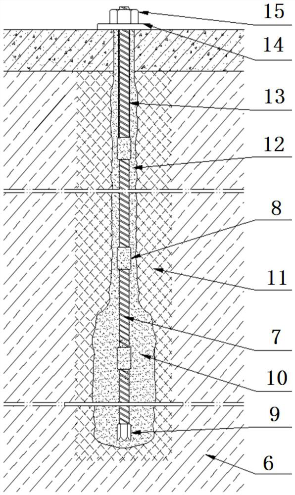
[0029] A structure system and construction method of a grout drilling, grouting, flushing and extruding expansion head bolt, such as figure 1 As shown, it includes multi-section hollow grouting anchor rods 7 installed along the axis of the anchor hole, and the upper and lower adjacent hollow grouting anchor rods 7 are connected and communicated through anchor joints 8 . The upper non-anchor free section hollow grouting anchor has an anti-corrosion layer ...


PUM


Abstract

The invention discloses a paste slurry drilling, grouting and impact extrusion expanded-head anchor rod structure system and a construction method thereof. According to the construction method, a self-drilling type hollow grouting anchor rod meeting the design requirement is directly used, and a drilling and grouting integrated in-situ impact extrusion grouting method is adopted, and middle-high pressure paste slurry impact extrusion drilling and grouting are conducted on full-hole section surrounding soil from top to bottom; and then a paste slurry pulse high-pressure pile squeezing and splitting method is adopted for conducting segmented reciprocating high-pressure paste slurry impact extrusion expanding grouting on an expanded-head anchoring hole section from bottom to top, after the expanded-head anchoring section meeting the design requirement is formed, middle-high pressure paste slurry impact extrusion drilling and grouting are conducted from top to bottom, and the self-drillingtype hollow grouting anchor rod is installed in place, so that the composite anchor rod structure system is formed, wherein the composite anchor rod structure system is combined with the self-drilling type hollow grouting anchor rod, and the composite anchor rod structure system is composed of upper non-anchored section middle-high pressure paste slurry impact extrusion grouting composite surrounding soil, a lower anchored section high-pressure paste slurry impact-extrusion expanded head pile body, a pile periphery slurry extrusion and splitting vein and a compacted soil body. The paste slurry drilling, grouting and impact extrusion expanded-head anchor rod structure system is convenient to construct, small in waste slurry amount, safe, environment-friendly and controllable in quality.

Description

technical field [0001] The invention relates to a structure system and a construction method of a grout-drilling-grouting-squeezing-extrusion-expanding-head bolt, belonging to the field of geotechnical anchoring engineering. Background technique [0002] The soil layer anchor is a tension rod body composed of a steel bar or steel strand and a grouting body in the hole, which is set in the borehole and the end extends into the stable soil layer. One end of it is connected with the engineering structure, and the other end is anchored in the In the soil layer, prestress is usually applied to it to bear the tension generated by earth pressure, water pressure or wind load, etc., to maintain the stability of the structure. [0003] According to the soil structure, engineering characteristics and use requirements, the anchor structure of the soil layer anchor can be divided into three types: cylindrical type, end enlarged head type or continuous spherical type. As for the end expa...

Claims


Application Information

Patent Timeline
Patent Type & Authority Applications(China)
IPC IPC(8): E02D3/08E02D5/74E02D5/44E02D15/04
CPCE02D3/08E02D5/44E02D5/74E02D15/04
Inventor 陈安重李永丰王少华曾来衡夏瑜斌黄超群
Owner POWERCHINA ZHONGNAN ENG
Why Eureka
Try Eureka