In-vivo phototherapy device with composite adjusting function

A phototherapy and functional technology, applied in phototherapy, therapy, radiation therapy, etc., can solve the problems of inconsistent overall shape, large loss of light energy of optical fiber, and large loss of light energy, and achieve the effect of avoiding radiation in non-patient areas

Pending Publication Date: 2022-02-08
GUAN YEOLIGHT TECH CO LTD
View PDF6 Cites 0 Cited by
  • Summary
  • Abstract
  • Description
  • Claims
  • Application Information

AI Technical Summary

Problems solved by technology

At present, the light source for in vivo treatment is mainly laser optical fiber. However, in actual use, the diseased area has the characteristics of uneven shape and inconsistent overall shape, which makes it difficult for the optical fiber to emit light therapy with uniform energy and suitable for the shape of the diseased area. The shape of the optical fiber leads to a large loss of light energy, and the light-emitting area is small, which is difficult to control
Therefore, we propose an in vivo phototherapy device with composite adjustment function to solve the above-mentioned problems of large loss of light energy, poor consistency of light emission, small light-emitting area and difficult to control

Method used


Image

  • In-vivo phototherapy device with composite adjusting function
  • In-vivo phototherapy device with composite adjusting function
  • In-vivo phototherapy device with composite adjusting function

Examples


Embodiment 1

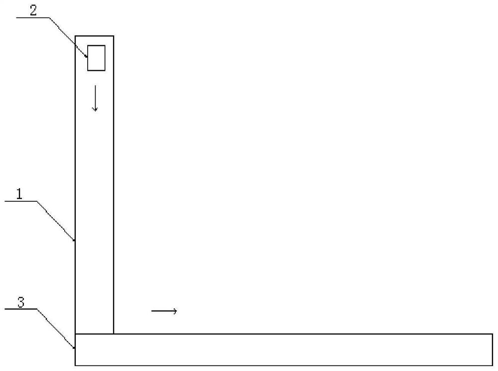
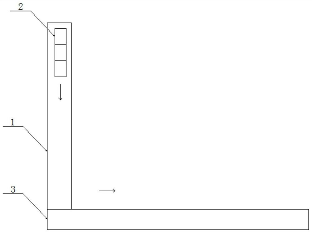
[0046] Please refer to Figure 1a and 1b The shown structure schematic diagram of a phototherapy device in the body with complex adjustment function provided by the present application includes:

[0047] Underframe 3 is made of a steel plate with a chute;

[0048] The bracket 1 is slidably installed on the bottom frame 3 along the first direction; wherein, a slider is fixed on the bottom of the bracket 1, and the slider can slide in the chute of the bottom frame 3, driving the bracket 1 along the chute to provide path movement;

[0049] Here, the first direction is the direction of the sliding path provided by the chute; and, the chute is provided on the support 1, and the chute is provided along the length direction of the support 1;

[0050] The light source 2 is slidably installed on the bracket 1 along the second direction, and is used to provide radiation light for treatment; wherein, the light source is fixed on a slider, and the slider can slide in the chute of the br...

Embodiment 2

[0094] In this embodiment, on the basis of Embodiment 1, the support movement area is three sections; there are three light source movement areas, which are respectively the first light source movement area, the second light source movement area and the third light source movement area; the total length of the support 1 is L=0.01m, in the first light source movement area, the length of the light source movement area is 0.008m, in the second light source movement area, the length of the light source movement area is 0.004m, in the third light source movement area, the length of the light source movement area is 0.008m; then in the first light source movement area and the third light source movement area, the light source movement speed u is greater than or equal to 0.04 m / s; then in the second light source movement area, the light source movement speed u is greater than or equal to 0.02 m / s;

[0095] set u 下 =0.4, L 下 = 0.004;

[0096] Then in the first light source movement ...

Embodiment 3

[0107] In this embodiment, on the basis of Embodiment 1, the support movement area is divided into two sections; there are two light source movement areas, which are respectively the first light source movement area and the second light source movement area; the total length of the support 1 is L=0.01m, In the first light source movement area, the length of the light source movement area is 0.01m, and in the second light source movement area, the length of the light source movement area is 0.006m; then in the first light source movement area, the light source movement speed u is greater than or equal to 0.05 m / s ; Then in the second light source movement area, the light source movement speed u is greater than or equal to 0.03 m / s;

[0108] set u 下 =0.4, L 下 = 0.004;

[0109] Then in the first light source movement area, the light source movement speed u=0.0016 / 0.01=0.16 m / s;

[0110] Then in the second light source movement area, the light source movement speed u=0.0016 / 0.0...


PUM


Abstract

The invention discloses an in-vivo phototherapy device with a composite adjusting function. The in-vivo phototherapy device comprises: a bottom frame; a bracket, which is mounted on the bottom frame in a sliding manner along a first direction; a light source, which is installed on the bracket in a sliding mode along a second direction and used for providing radiation light for treatment; a first driving mechanism, which is arranged on the bottom frame and used for driving the bracket to slide back and forth in the first direction; and a second driving mechanism, which is arranged on the bracket and used for driving the light source to slide back and forth in the second direction. The light source is installed on the bracket, and a treatment area of the corresponding shape is formed by controlling the movement speed of the bracket and the light source; the light source and/or the bracket are/is controlled by the driving mechanisms to move, and the shape and size of the radiation area of the light source are adjusted by adjusting the movement speed of the light source and/or the bracket, so that the shapes and sizes of different patient areas are met, and non-patient areas can be prevented from being radiated.

Description

technical field [0001] The present disclosure generally relates to the technical field of optical medical equipment, and in particular relates to an in vivo phototherapy device with compound adjustment functions. Background technique [0002] Phototherapy includes photodynamic therapy (PDT), in which light with a specific wavelength or waveband is irradiated to target cells, and the target cells are made photosensitized by taking a photoreactive agent, a photoactivator or a photosensitizer. Photoreactive agents have specific light absorption bands and are typically administered to the patient intravenously, orally, or by topical delivery to the treatment site. Often abnormal cells in the body can selectively absorb specific light-reactive agents far in excess of the normal amount of healthy cells. Abnormal cells can be treated by exposing the cells to light of the appropriate wavelength or band when they have absorbed a photoreactive agent and / or become molecularly attached...

Claims


Application Information

Patent Timeline
Patent Type & Authority Applications(China)
IPC IPC(8): A61N5/06
CPCA61N5/062A61N2005/0633A61N2005/0651A61N2005/0653A61N2005/0626A61N2005/0662
Inventor 郭立雪朱映光胡永岚谢静王静
Owner GUAN YEOLIGHT TECH CO LTD
Why Eureka
Try Eureka