Cutting tool

A technology for cutting tools and casings, which is applied in manufacturing tools, metal sawing equipment, metal processing equipment, etc., and can solve the problems of unfavorable motor performance, long-term operation, large volume, etc.

Pending Publication Date: 2022-07-01
NANJING CHERVON IND
View PDF0 Cites 0 Cited by
  • Summary
  • Abstract
  • Description
  • Claims
  • Application Information

AI Technical Summary

Problems solved by technology

Existing cutting tools are bulky and the performance

Method used


Image

  • Cutting tool
  • Cutting tool
  • Cutting tool

Examples


Embodiment Construction

[0036] The present invention will be described in detail below with reference to the accompanying drawings and specific embodiments.

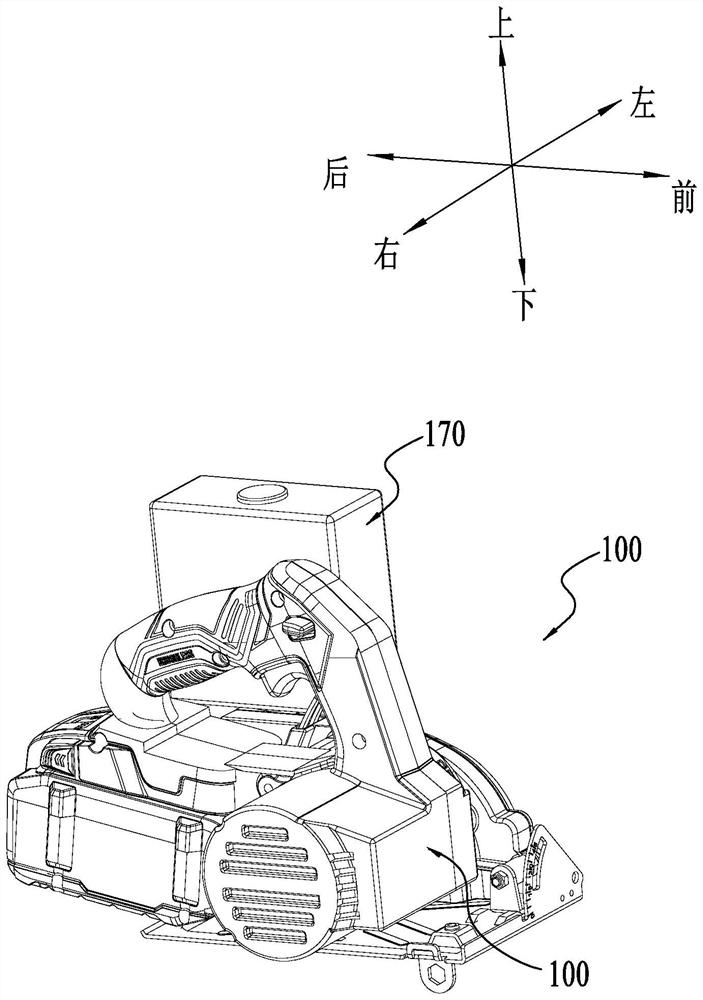
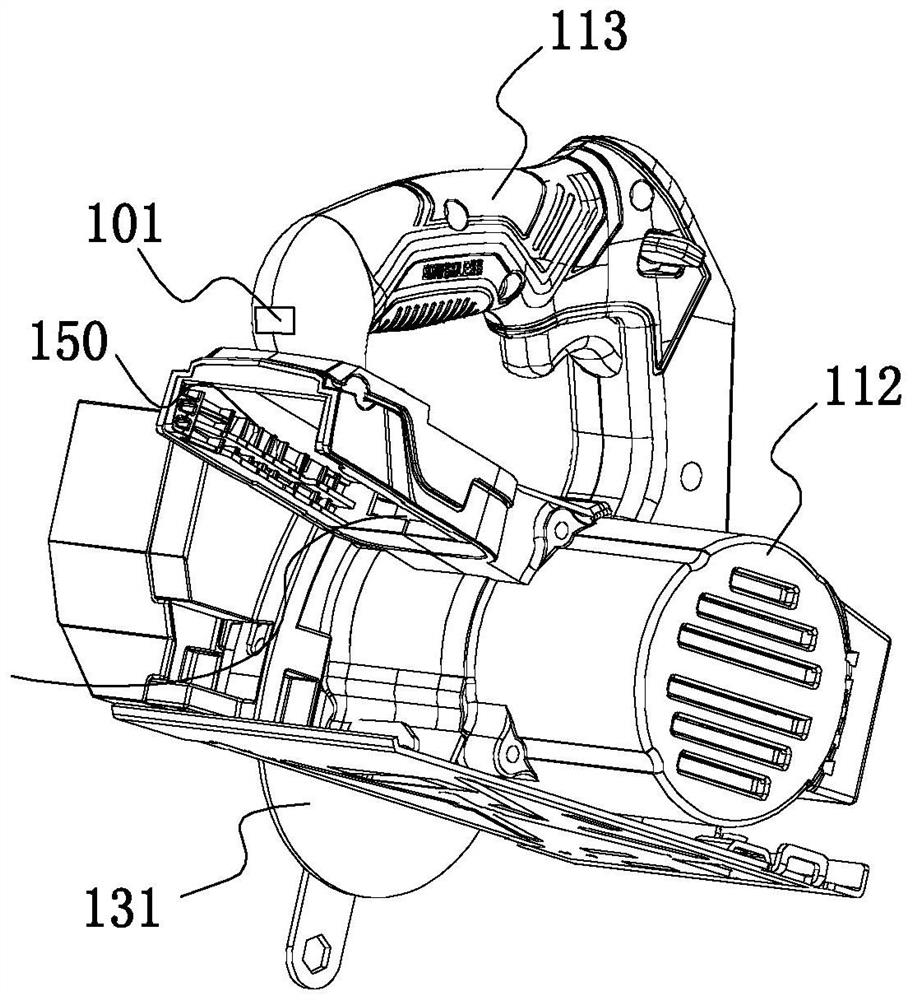
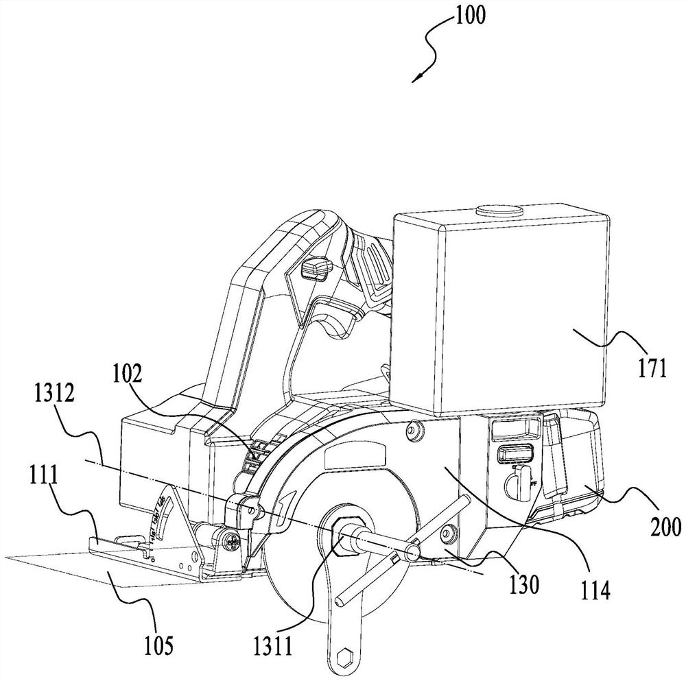
[0037] In one embodiment of the present invention, refer to Figure 1 to Figure 3 , to provide a cutting tool 100, specifically a marble machine, which can be used to cut workpieces such as stone, and grinds and cuts the stone by driving the grinding disc 131 to rotate. The cutting tool 100 includes a housing 110 , a motor 120 , an accessory mounting portion 130 and a transmission mechanism 140 , the motor 120 is supported by the housing 110 , the accessory mounting portion 130 includes an output member 1311 connected to the grinding disc 131 , and the transmission mechanism 140 connects the output member and the motor 120. The cutting tool 100 also includes a power interface 150 for accessing a power source. In one embodiment, the power source may be AC ​​mains. In one embodiment, the power source is a DC power source, such as a battery pac...


PUM

PropertyMeasurementUnit
Diameteraaaaaaaaaa

Abstract

The present invention provides a cutting tool comprising: a motor supported by a housing; the accessory mounting part comprises an output piece connected with the grinding disc; the transmission mechanism is connected with the motor and the output piece; the bottom plate is arranged at the bottom of the shell and is provided with a mounting hole for the millstone to penetrate through; the liquid storage system comprises a liquid storage device used for storing liquid, and the liquid storage device is detachably installed on the shell; and the system control piece is arranged on a liquid flowing path of the liquid storage system and is used for controlling the flowing state of the liquid in the liquid storage device. The cutting tool is good in cutting performance, the whole structure of the cutting tool is optimized, and the cutting tool is small in size and convenient to operate.

Description

technical field [0001] The present invention relates to electric tools, in particular to a cutting tool. Background technique [0002] The cutting tool is used to cut the workpiece and is provided with a base plate for assisting the cutting action. The existing cutting tools are bulky, and the motor performance is not conducive to long-term operation. SUMMARY OF THE INVENTION [0003] The main purpose of the present invention is to provide a cutting tool, the overall structure of the cutting tool is optimized, and the performance is improved, so that the size of the cutting tool is small and easy to operate. [0004] In order to achieve the above main purpose of the invention, a cutting tool is provided, comprising: a casing; a motor, supported by the casing; an accessory mounting part, including an output member connected to a grinding disc; a transmission mechanism, connected to the motor and the output member a bottom plate, which is arranged at the bottom of the casi...

Claims


Application Information

Patent Timeline
IPC IPC(8): B24B27/08B24B55/02
CPCB24B27/08B24B55/02B24B55/03B24B53/007B24B55/05B25F5/00B25F5/02H01M10/6562H01M10/6235H01M10/613B27B9/00B23D47/12B23D59/001B23D59/02B23D45/16
Inventor 王荣王少君
Owner NANJING CHERVON IND
Why Eureka
Try Eureka