Fan shaft assembly

A technology for fan shafts and assemblies, applied in the field of fan shaft assemblies, can solve the problems such as the inability to meet the layout requirements of the whole machine, the large installation clearance of the fan shaft assemblies, and the impact on the working environment of the bearings, so as to reduce the weight of parts, increase the strength, and reduce the installation size. gap effect

Active Publication Date: 2017-06-13
GUANGXI YUCHAI MASCH CO LTD
View PDF8 Cites 0 Cited by
  • Summary
  • Abstract
  • Description
  • Claims
  • Application Information

AI Technical Summary

Problems solved by technology

[0003]The installation clearance of the existing fan shaft assembly is large, dust, muddy water and other sundries can easily enter the working space of the bearing, affecting the working environment of the bearing
In addition, the bearing seat of the existing fan shaft assembly has a single structure and function, which cannot meet the different layout requirements of the whole machine

Method used


Image

  • Fan shaft assembly
  • Fan shaft assembly
  • Fan shaft assembly

Examples


Embodiment Construction

[0016] The specific embodiments of the present invention will be described in detail below in conjunction with the accompanying drawings, but it should be understood that the protection scope of the present invention is not limited by the specific embodiments.

[0017] Unless expressly stated otherwise, throughout the specification and claims, the term "comprise" or variations thereof such as "includes" or "includes" and the like will be understood to include the stated elements or constituents, and not Other elements or other components are not excluded.

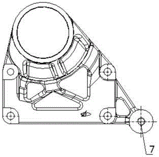
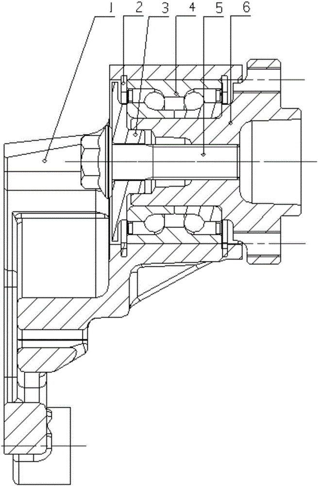
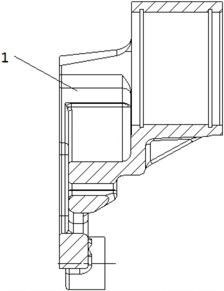
[0018] Such as figure 1 As shown, the fan shaft assembly according to the specific embodiment of the present invention specifically includes: a bearing seat 1 , a baffle 3 , a bearing 4 and a fan shaft 6 . Wherein, the bearing 4 is installed on the bearing seat 1, and two retaining rings and the upper limit groove of the bearing seat 1 are used for axial positioning to control the axial movement of the bearing. The fan sh...


PUM


Abstract

The invention discloses a fan shaft assembly. The fan shaft assembly comprises a bearing seat, a bearing, a fan shaft and a baffle, wherein a bearing mounting hole is formed in one end of the bearing seat, an idle wheel mounting support is integrated at the other end of the bearing seat, and an idle wheel mounting threaded hole is formed in the idle wheel mounting support; the outer ring of the bearing is mounted in the bearing mounting hole of the bearing seat; the fan shaft is inserted in the inner ring of the bearing, a baffle insertion hole is formed in one end of the fan shaft, and a bolt hole is formed in the middle of the fan shaft; and a bolt through hole is formed in the center of the baffle, and a bearing insertion head is arranged at one end of the baffle, inserted into the baffle insertion hole of the fan shaft and fixed through a bolt penetrating through the bolt through hole and the bolt hole. According to the fan shaft assembly, the baffle and the bearing are both positioned through the fan shaft, so that a mounting gap is narrowed, the probability that impurities such as dust and muddy water enter the working space of the bearing can be greatly lowered, and the working environment of the bearing is optimized. Meanwhile, the idle wheel mounting and supporting support is integrated, and thus a wheel train can be arranged more compactly.

Description

technical field [0001] The invention relates to the field of engine clutches, in particular to a fan shaft assembly. Background technique [0002] The fan shaft assembly is mainly used to provide fixation, support and output power for the fan. It drives the fan pulley to rotate through the force of the belt to provide power for the fan and provide sufficient air flow to meet the functional requirements of the engine cooling system. [0003] The installation gap of the existing fan shaft assembly is large, dust, muddy water and other sundries can easily enter the working space of the bearing, affecting the working environment of the bearing. In addition, the bearing seat of the existing fan shaft assembly has a single structure and function, which cannot meet different layout requirements of the whole machine. [0004] The information disclosed in this Background section is only for enhancing the understanding of the general background of the present invention and should not...

Claims


Application Information

Patent Timeline
Patent Type & Authority Applications(China)
IPC IPC(8): F04D29/05F04D29/053F04D29/056
CPCF04D29/05F04D29/053F04D29/056F04D29/0563Y02E10/72
Inventor 卢猛黄志云陶正勇何化李国红
Owner GUANGXI YUCHAI MASCH CO LTD
Why Eureka
Try Eureka