Oxygen-enriching machine

A technology of an oxygenation device and aerator, which is used in water/sludge/sewage treatment, animal husbandry, mixing methods, etc., can solve the problems of affecting the oxygenation effect, uneven oxygenation of water bodies, and reduced water flow, etc. The structure of the whole machine is improved, which is conducive to maintenance and reduces the air resistance.

Inactive Publication Date: 2005-09-14
吴勇
View PDF0 Cites 0 Cited by
  • Summary
  • Abstract
  • Description
  • Claims
  • Application Information

AI Technical Summary

Problems solved by technology

Problems in this working method: 1. The pump body and blades are subjected to cavitation impact, which affects the service life of the pump, reduces efficiency, and generates vibration
2. The amount of air inhaled is limited
Because the pump body has no air flow when there is no water flow, when the pump body is started, the air flow rate increases with the increase of the water flow rate. capacity, resulting in the reduction of water flow, the air flow will also decrease, and the reduction of air flow will affect the effect of oxygenation
3. When the pump body is working, the air-water mixture is sprayed from one side of the lower part of the pump body, so that the pump body is subjected to the reaction force of the water. The greater the output force of the pump, the greater the reaction force. In order to keep the pump body still on the water surface, a rope has to be used. Fixed, it is inconvenient to fix the pump body when the water surface is very large and the water is very deep, and it also makes the whole water body oxygenate unevenly

Method used


Image

  • Oxygen-enriching machine
  • Oxygen-enriching machine
  • Oxygen-enriching machine

Examples


Embodiment Construction

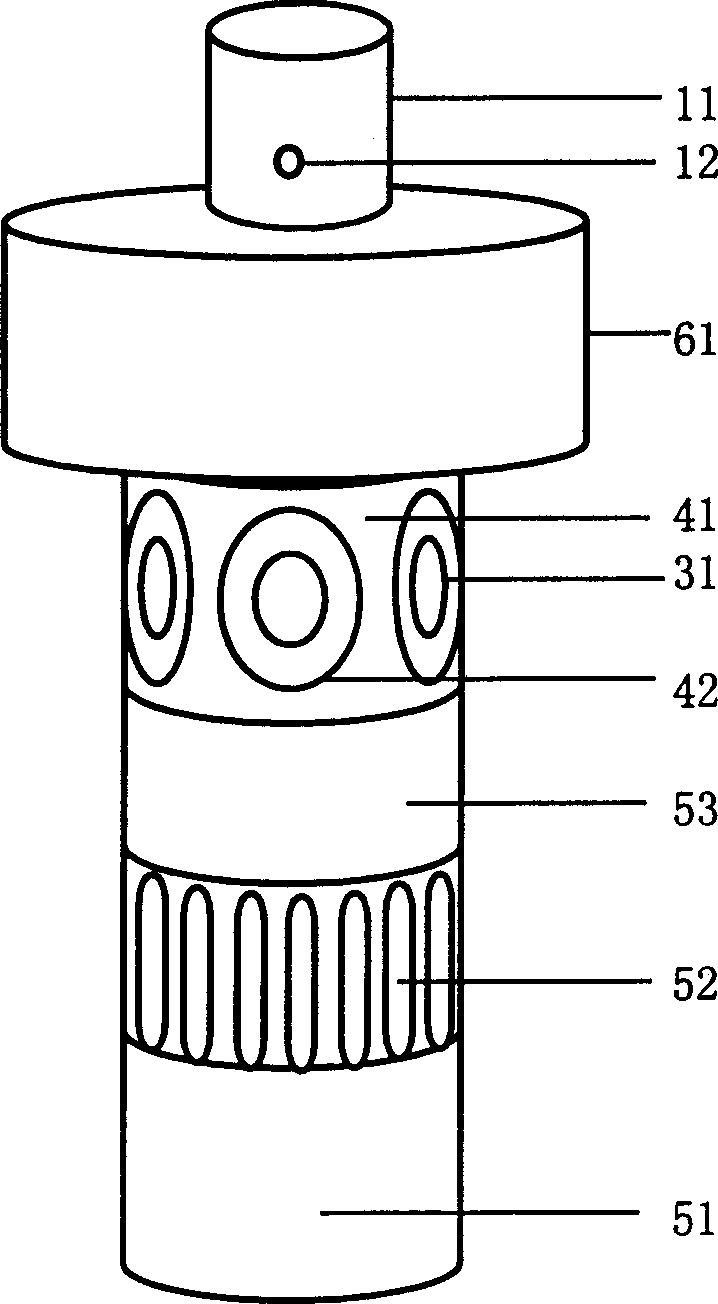
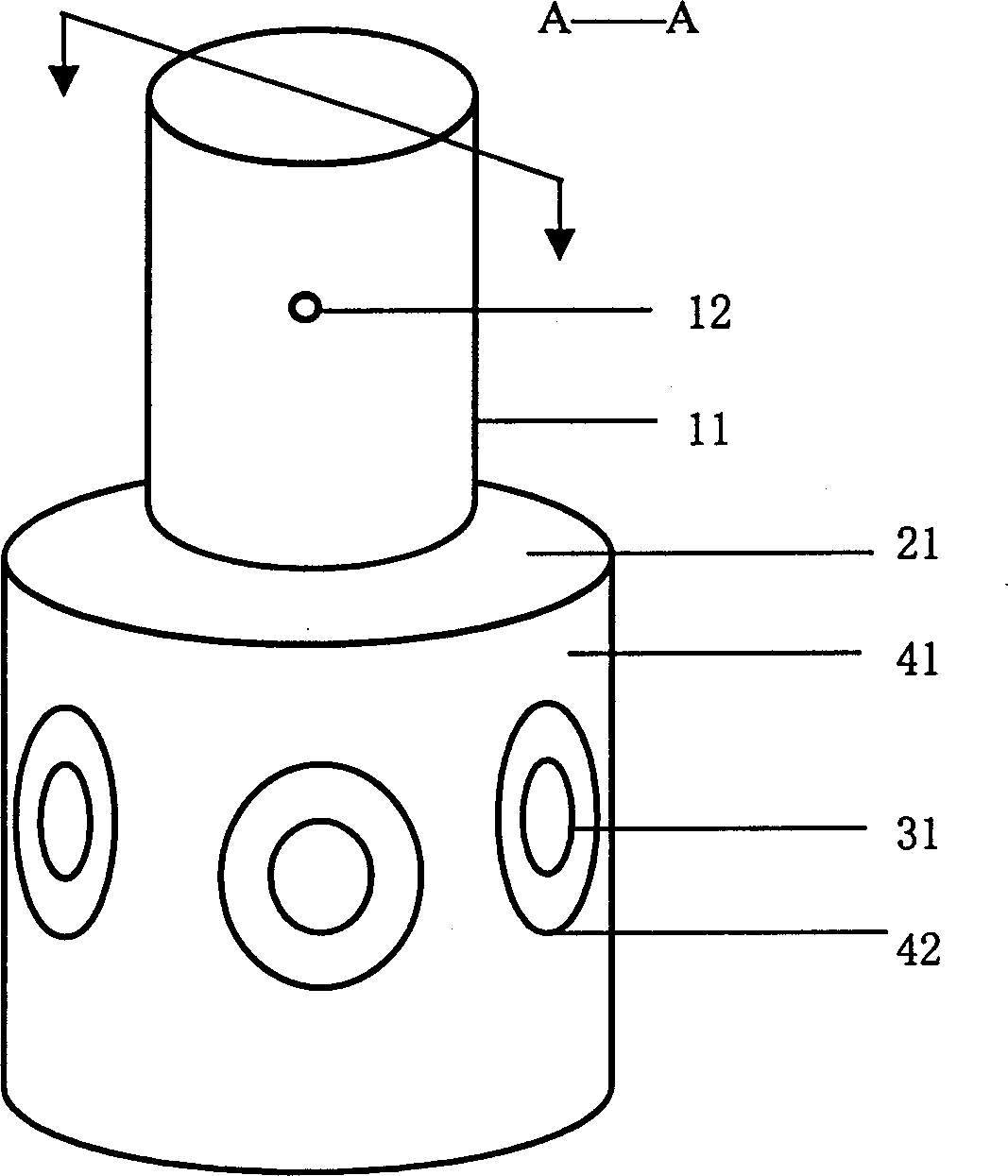
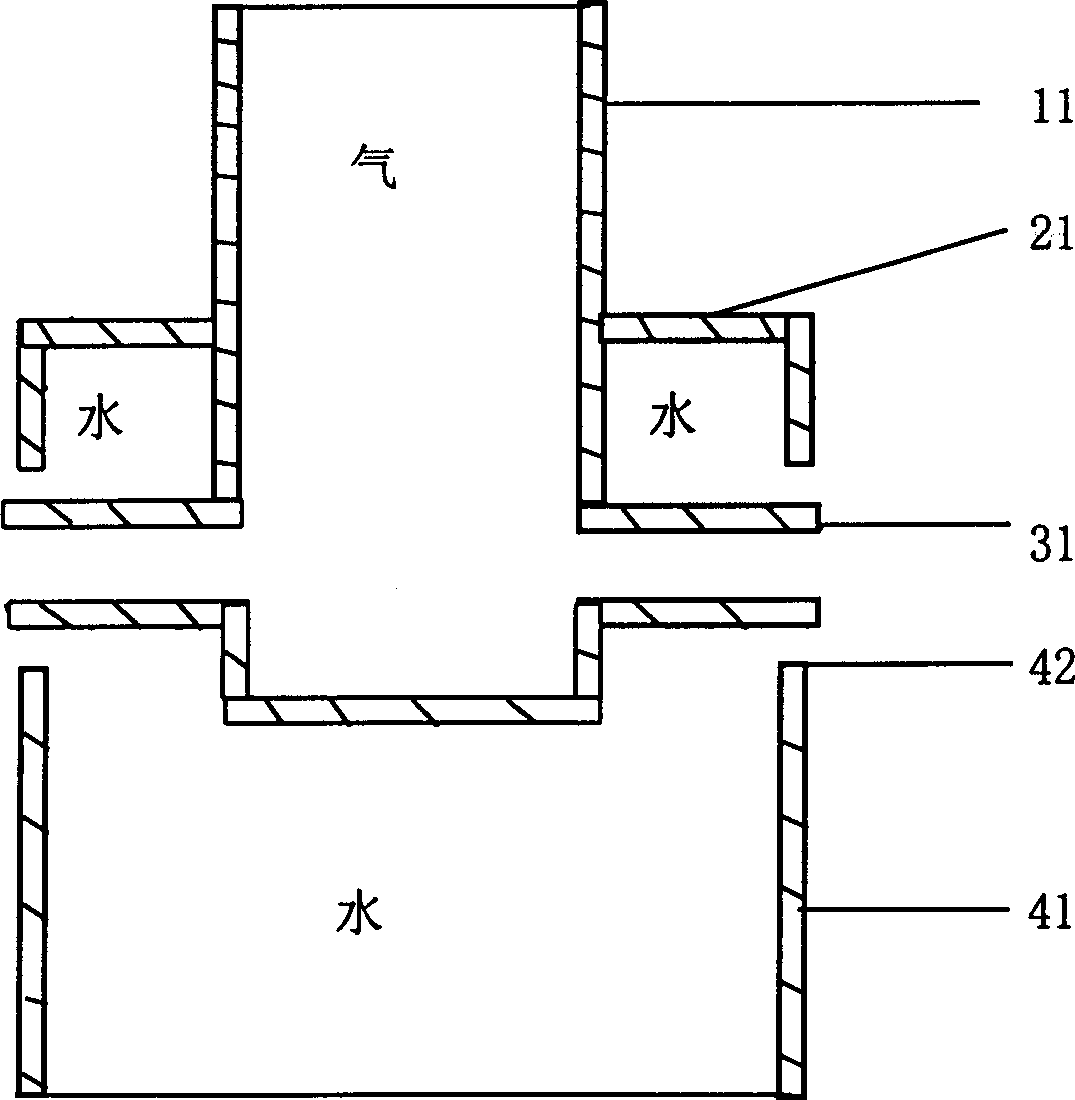
[0015] Preferred embodiments of the present invention such as figure 1 , wherein the gas main pipe 11, the jellyfish pipe 41, and the air branch pipe 31 all adopt a cylindrical structure, and the nozzle hole 42 is a circular hole. The outlet of the gas branch pipe 31 and the nozzle hole 42 form a double-channel nozzle. The air main pipe 11 communicates with the air branch pipe 31 to form an air passage. The space surrounded by the outer wall of the gas branch pipe 31 and the nozzle hole 42 constitutes a water channel. The geometric dimensions of the six double-channel nozzles are equal, and the angles between them are each 60 degrees. When working, the upper mouth of the gas main pipe is exposed to the water surface, the whole machine is vertical to the water surface and floats in the water body, and the 6 double-channel nozzles are below the water surface. The water in the lower layer enters the filter screen 52, and under the action of the pump body 53, this part of the w...


PUM


Abstract

A dual-channel nozzle-type oxygen-enriching machine for aquatic farm is composed of submerged pump, water trunk, dual-channel nozzle, air trunk, air branch pipes, step and buoy. Its advantages are no interference between water and air channels, high air flow, and uniform oxygen enriching in water.

Description

(1) Technical field: [0001] The invention relates to a device for aerating and dissolving oxygen in a water body. (two) background technology: [0002] In the prior art, the structure of the submersible aerator is to insert a suction pipe into the water inlet of the submersible pump, and the other end of the pipe is open to the atmosphere. When the pump is working, the water flow rate is established in the water inlet, and the vacuum pressure is generated at the outlet of the suction pipe. , Air in the suction pipe flows into the pump body, and the mixture of water and air is sprayed out from the pump outlet through the impeller. Problems in this mode of operation: 1. The pump body and blades are subjected to cavitation impact, which affects the service life of the pump, reduces efficiency, and generates vibration. Because the density of air and water is 700 times different, when the pump is working, the high-speed air and water flow hit the pump body and blades, and the st...

Claims


Application Information

Patent Timeline
IPC IPC(8): A01K61/00A01K63/04B01F3/04C02F7/00
CPCY02A40/81Y02W10/10
Inventor 吴勇
Owner 吴勇
Why Eureka
Try Eureka