Heat pump electricity storage system based on carbon dioxide working medium and operation method

A technology of carbon dioxide and working medium, applied in the field of heat pump power storage system based on carbon dioxide working medium, can solve the problems of insufficient compact structure and complicated preparation of working medium, and achieve long energy storage period, high energy storage density and high power density. Effect

CN114810254APending Publication Date: 2022-07-29XI AN JIAOTONG UNIV
3 Cites 0 Cited by

Patent Information

Authority / Receiving Office
CN · China
Patent Type
Applications(China)
Current Assignee / Owner
Publication Date
2022-07-29

Smart Images

  • Figure 1
    Figure 1
  • Figure 2
    Figure 2
  • Figure 3
    Figure 3
Patent Text Reader

Abstract

The invention discloses a heat pump electricity storage system based on a carbon dioxide working medium and an operation method. The system comprises high-temperature heat storage, a heat pump cycle and a heat engine cycle. During charging, redundant electric power is used for driving the heat pump to circulate, and electric energy is converted into high-grade heat energy to be stored in the high-temperature heat storage tank; during discharging, stored heat energy is converted into electric energy to be released through heat engine circulation. The heat pump and the heat engine cycle both adopt carbon dioxide as a working medium, the cold end of the system is connected with the environment, according to the environment temperature, the heat pump cycle selects a transcritical operation mode or a supercritical operation mode, and the heat engine cycle selects a supercritical operation mode. The heat pump cycle adopts simple heat regeneration arrangement, and the heat engine cycle adopts recompression arrangement. Carbon dioxide serves as a working medium, the structure is compact, efficiency is high, meanwhile, the cold end of the system is connected with the environment, cold storage or low-temperature heat storage is not needed, tank arrangement can be reduced, the structure is simplified, and the energy storage density is high. The method can be used for stabilizing power grid fluctuation, promoting new energy consumption and adjusting power grid stability.
Need to check novelty before this filing date? Find Prior Art

Description

technical field

[0001] The invention belongs to the technical field of energy storage, and in particular relates to a carbon dioxide-based heat pump power storage system and an operation method. Background technique

[0002] In recent years, my country has actively promoted the construction of a new power system with new energy as the main body, but the renewable energy power generation (wind energy, photovoltaic, etc.) system is intermittent, fluctuating and random, resulting in the flexibility and adjustment ability of the power system. high demands. Therefore, the power system needs more flexible and controllable technologies to participate, and the rapidly developing energy storage technology is an effective way to improve the flexibility of the power system.

[0003] Heat pump power storage technology is a new type of large-scale energy storage technology. Compared with traditional compressed air energy storage and pumped hydro storage, this technology has no geographic...

Examples

Embodiment Construction

[0026] The present invention will be further described in detail below with reference to the accompanying drawings and specific embodiments.

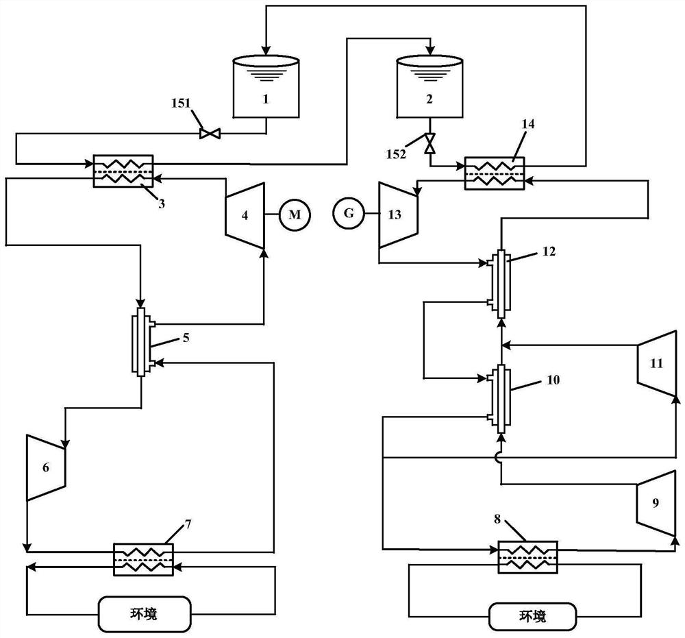
[0027] like figure 1 As shown, the present invention is a heat pump power storage system based on carbon dioxide working medium, which mainly includes a high temperature heat storage module, a heat pump circulation module and a heat engine circulation module;

[0028] The high temperature heat storage module is mainly composed of high temperature heat storage-cold tank 1, high temperature heat storage-hot tank 2, high temperature heat exchanger I3, high temperature heat exchanger II14, valve I151 and valve II152. The outlet of the high temperature heat storage-cold tank 1 is connected to the cold side inlet of the high temperature heat exchanger I3 through the valve I151, and the cold side outlet of the high temperature heat exchanger I3 is connected to the inlet of the high temperature heat storage-heat tank 2, and the high temperature...