Gyrotron and electronic device using same

A technology of vibrating gyroscopes and vibrators, which is applied in the direction of measuring devices, gyroscope effects for speed measurement, gyroscope/steering sensing equipment, etc., and can solve the problems of high height of vibrating gyroscopes installed on the substrate and violation of low height tendency

Inactive Publication Date: 2006-04-12
MURATA MFG CO LTD
View PDF1 Cites 0 Cited by
  • Summary
  • Abstract
  • Description
  • Claims
  • Application Information

AI Technical Summary

Problems solved by technology

[0007] However, increasing the thickness of the mounting substrate means that the height of the vibrating gyro itself has increased, which is contrary to the recent trend of lowering the height of most electronic components.

Method used


Image

  • Gyrotron and electronic device using same
  • Gyrotron and electronic device using same
  • Gyrotron and electronic device using same

Examples


Embodiment Construction

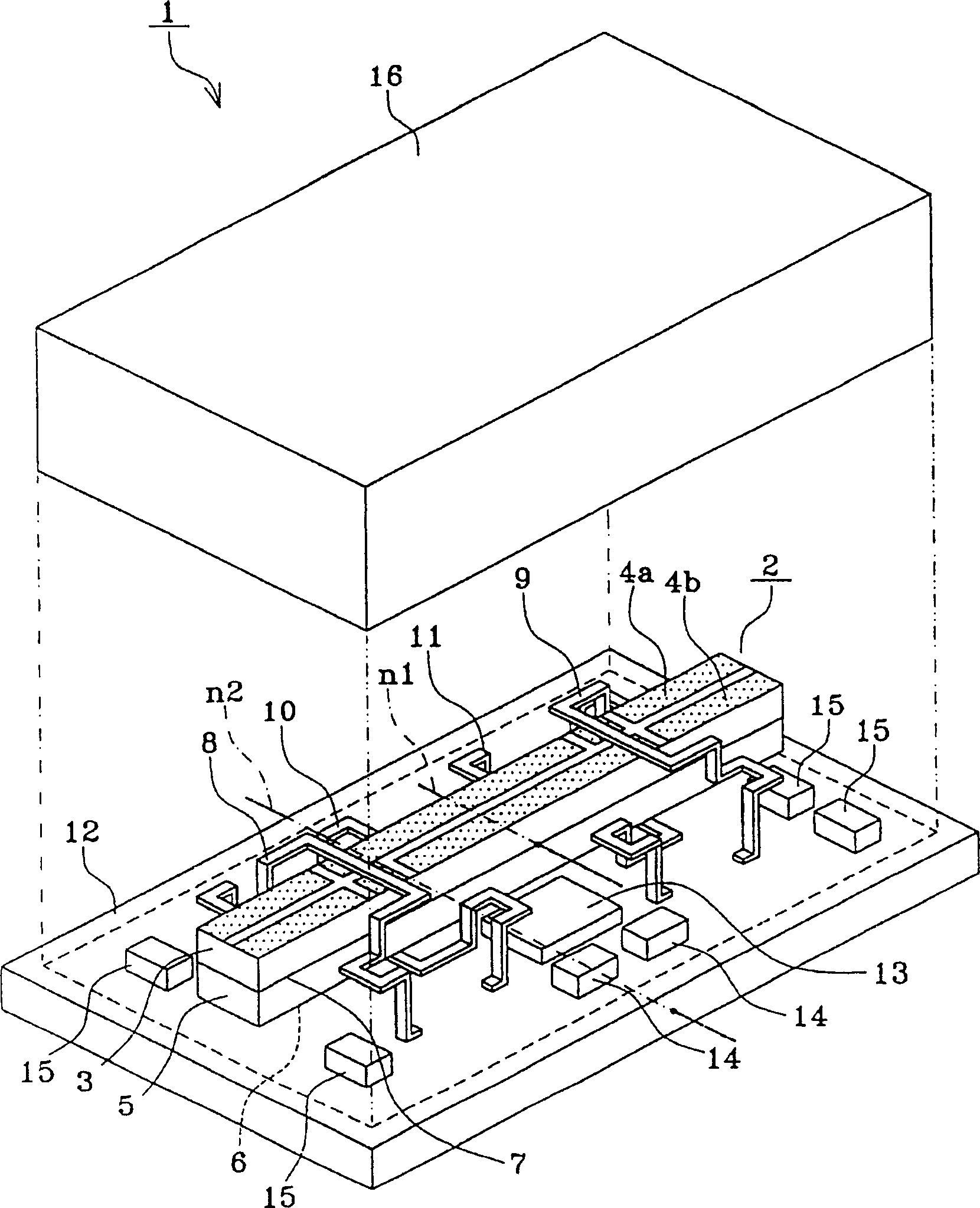
[0019] figure 1 A perspective view showing an embodiment of the vibrating top of the present invention. exist figure 1 Among them, the top 1 has: a vibrator 2; conductive support members 8, 9, 10, 11 made of metal such as plate-shaped Fe-Ni containing gold or phosphor bronze; a mounting substrate 12; the vibrator 2 is excited and flexurally vibrated Components 13 , 14 , 15 for a drive detection circuit that detect an angular velocity applied to the vibrator 2 from a signal output from the vibrator 2 ; and a cover 16 .

[0020] The vibrator 2 is formed by forming the piezoelectric substrate 3 with the electrodes 4a and 4b separated in the width direction on one main surface while being polarized in the thickness direction, and forming the piezoelectric substrate 3 on one main surface while being polarized in the thickness direction. The piezoelectric substrate 5 of the electrode 6 is bonded to each other on the other main surface via the electrode 7 to form a bimorph structur...


PUM


Abstract

A column shape vibrator (2) that produces bending vibration with both ends unsupported is mounted on one principal surface of a mounting board (12), and a driving-and-detecting circuit component (13) is also mounted to cross over an antinode center line (n2) of bending vibration of the mounting board (12) due to resonance. The original self-resonance frequency of bending vibration of the mounting board (12) itself is lower than the frequency of bending vibration of the vibrator (2). The modified self-resonance frequency of bending vibration of the mounting board when the vibrator (2) and the driving-and-detecting circuit component (13) are mounted thereon is higher than the original self-resonance frequency, and does not coincide with the frequency of bending vibration of the vibrator (2). The invention provides a vibrating gyro which comprises a thin mounting board, whose height is low and whose characteristic change is small between its characteristic adjustment before mounting a cover and its completion after mounting the cover, and provides an electronic device using the vibrating gyro.

Description

technical field [0001] The present invention relates to a vibrating top and an electronic device using the same. For example, it relates to a vibrating top used in a manual correction device of a television camera and an electronic device using the same. Background technique [0002] A vibrating gyroscope has been disclosed in, for example, Fig. 6 of JP-A-2001-227953 (hereinafter referred to as Existing Example 1). The structure of this vibrating gyroscope is that the node portion is supported by a supporting member so that the longitudinal direction of the vibrator and the installation One main surface of the substrate is parallel, and a columnar vibrator performing bending vibration with open ends is mounted on one main surface of the mounting substrate. [0003] In Conventional Example 1, the vibrator 100 is mounted on one main surface of the mounting substrate 20 (12) by supporting the nodes thereof with the supporting members 104 (8), 105 (9), 106 (10), and 107 (11). (...

Claims


Application Information

Patent Timeline
Patent Type & Authority Patents(China)
IPC IPC(8): G01C19/56G01C19/5628G01C19/5663
CPCG01C19/5663Y10T74/1275
Inventor 藤本克己冈野惠一小池雅人山本浩诚
Owner MURATA MFG CO LTD
Why Eureka
Try Eureka