Switching circuit

A switching circuit and circuit technology, applied in electronic switches, emergency protection circuit devices, electrical components, etc., can solve problems such as inability to properly protect switching components

Active Publication Date: 2019-01-25
TOYOTA JIDOSHA KK
View PDF4 Cites 0 Cited by
  • Summary
  • Abstract
  • Description
  • Claims
  • Application Information

AI Technical Summary

Problems solved by technology

However, in this control method, when the current increases rapidly (that is, when the rate of increase of the current is very high), the current may increase to a higher value during the period from when the current exceeds the threshold value until the switching element is turned off. Failure to properly protect switching elements

Method used


Image

  • Switching circuit
  • Switching circuit
  • Switching circuit

Examples


Embodiment Construction

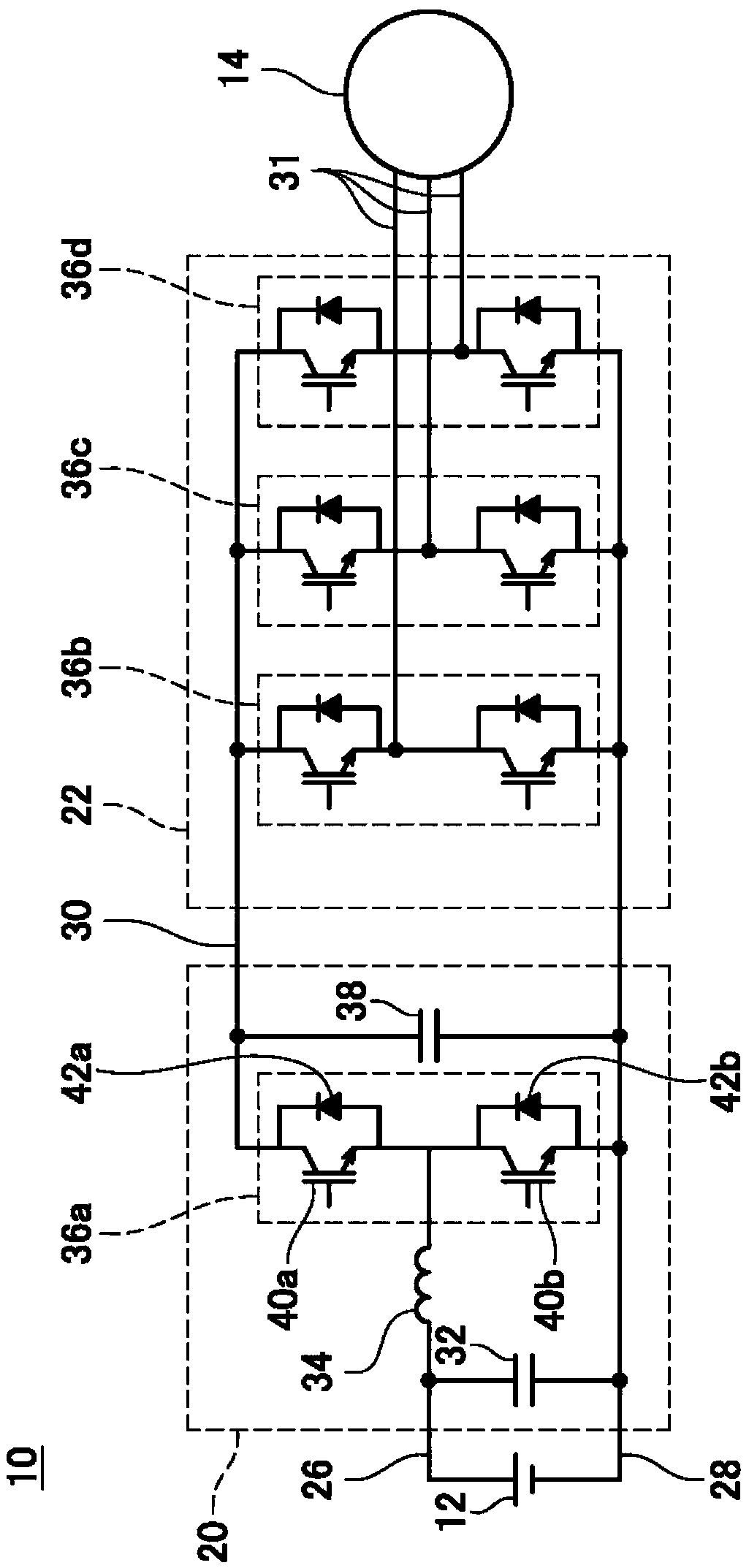
[0013] The switching circuit of this embodiment is built into the figure 1 The motor drive circuit 10 is shown. The motor drive circuit 10 is mounted on a vehicle. The motor drive circuit 10 converts the DC power of the battery 12 into three-phase AC power, and supplies it to the running motor 14 . The motor drive circuit 10 has a converter circuit 20 and an inverter circuit 22 . The battery 12 and the conversion circuit 20 are connected by a first high potential wiring 26 and a low potential wiring 28 . The conversion circuit 20 and the inverter circuit 22 are connected by a second high potential wiring 30 and a low potential wiring 28 .

[0014] The conversion circuit 20 has a smoothing capacitor 32 , a reactor 34 , a series circuit 36 ​​a of switching elements, and a smoothing capacitor 38 . A reactor 34 is installed in the first high potential wiring 26 . The smoothing capacitor 32 is connected between the first high potential wiring 26 and the low potential wiring 28...


PUM


Abstract

A switching circuit includes: a detection wiring configured to receive a potential changing depending on a current of a first switching element; a first circuit connected between the detection wiringand a first having a first time constant, and making the first wiring follow the potential of the detection wiring; a second circuit connected between the detection wiring and a second wiring, havinga second time constant larger than the first time constant, and making the second wiring fellow the potential of the detection wiring; a potential maintaining circuit configured to maintain the secondwiring at a potential higher than the potential of the first wiring while a current is not flow through the first switching element; and a control circuit configured to turn off the first switching element in a case where the potential of the first wiring exceeds the potential of the second wiring.

Description

technical field [0001] The technology disclosed in this invention relates to switching circuits. Background technique [0002] There is known a switching circuit that controls current by switching a switching element. In some cases, an overcurrent may flow through the switching element due to a short circuit of another element connected to the switching element. When an overcurrent flows, it is necessary to turn off the switching element as soon as possible to protect the switching element. One control method for protecting the switching element from overcurrent is to turn off the switching element when the current flowing through the switching element exceeds a threshold value. However, in this control method, when the current increases rapidly (that is, when the rate of increase of the current is very high), the current may increase to a higher value during the period from the current exceeding the threshold value until the switching element is turned off. Switching ele...

Claims


Application Information

Patent Timeline
Patent Type & Authority Applications(China)
IPC IPC(8): H02H7/12
CPCH02H7/1213H02M1/32H02M1/38H02H7/1225H03K17/0828H02M1/0009H02H7/1227H02H1/0007H02M7/5395H02M1/088
Inventor 利行健
Owner TOYOTA JIDOSHA KK
Why Eureka
Try Eureka