Multi way switch

A multi-directional switch and switch technology, used in electrical switches, switch lubrication, mechanical control devices, etc., can solve the problems of bad feeling of sticking and the feeling of not being able to get stuck.

Inactive Publication Date: 2002-10-16
ALPS ALPINE CO LTD
View PDF0 Cites 1 Cited by
  • Summary
  • Abstract
  • Description
  • Claims
  • Application Information

AI Technical Summary

Problems solved by technology

[0033] In the above-mentioned multi-directional switch device, because the click feeling is produced by the very small longitudinal bending of the two conical parts 52d, it is impossible to obtain a sufficient click feel.
[0034] In addition, in the above-mentioned multidirectional switch device, the smooth lower surface of the protruding portion 53c of the operating member 53 and the smooth upper surface of the pressing portion 52c of the rubber dome 52a are always in close contact with each other. During the tilting operation, since the protruding portion 53c presses the pressing portion 52c in a tight contact state, the conical portion 52d bends vertically while being pushed in the direction of the arrow Z, resulting in a bad click feeling.

Method used


Image

  • Multi way switch
  • Multi way switch
  • Multi way switch

Examples


Embodiment Construction

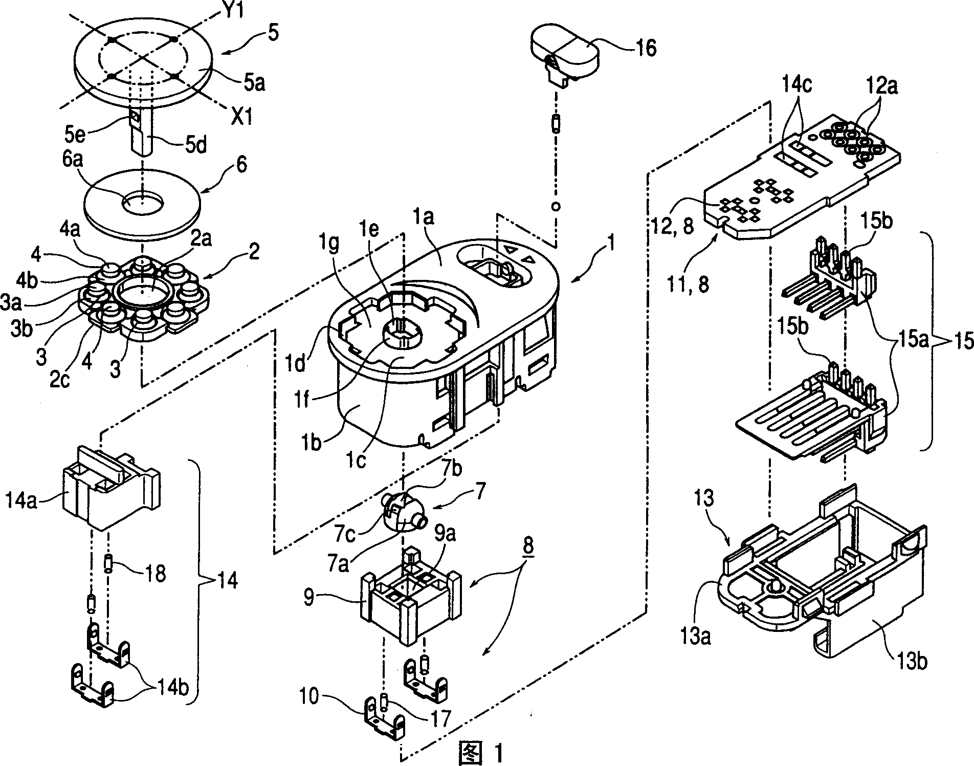
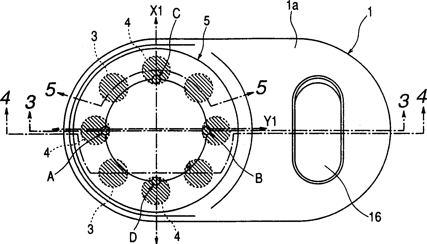
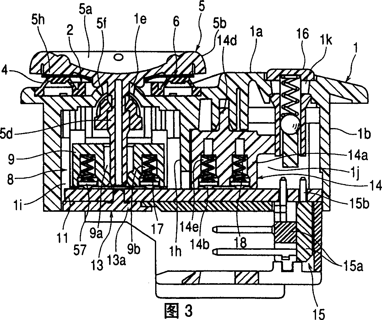
[0069] The accompanying drawings of the multidirectional switch device of the present invention are explained below. Fig. 1 is an exploded perspective view showing a multidirectional switch device of the present invention, figure 2 It is a plan view showing the multidirectional switch device of the present invention, and Fig. 3 is figure 2 A sectional view on line 3-3 of the Figure 4 yes figure 2 A sectional view on line 4-4 of the Figure 5 Relating to the multi-directional switch device of the present invention, it means elastic spring member and thin plate member figure 2 Sectional view on line 5-5.

[0070] The box 1 made of synthetic resin has: a nearly flat upper wall 1a; a side wall 1b extending vertically from the vicinity of the outer periphery of the upper wall 1a and surrounding the surrounding; a substantially quadrangular recess 1c provided on the upper left of the upper wall 1a ; the groove portion 1d provided at the four corners of the recessed portion...


PUM


Abstract

A multi-directional switch device arrangement, comprising: a box body 1; a plurality of switches 8 accommodated in the box body 1; an operating member 5 that can be tilted in multiple directions and operate the switches by tilting in various directions; The first rubber dome 3 operated by the tilting action of the operating member; the second rubber dome 4 arranged in the vicinity of the first rubber dome. The movable distance of the second rubber dome based on the dumping action of the operating member is longer than the movable distance of the first rubber dome.

Description

technical field [0001] The invention particularly relates to a multidirectional switch device suitable for electric window mirrors of vehicles. Background technique [0002] Below, the accompanying drawing of existing multidirectional switch device is described, Figure 7 It is a top view showing an existing multidirectional switch device, and Fig. 8 is Figure 7 A sectional view on line 8-8 of the Figure 9 Related to the existing multi-directional switch device, it means the elastic spring member Figure 7 Sectional view on line 9-9 in, Figure 10 yes Figure 7 Sectional view on line 10-10 in. [0003] The box body 51 made of synthetic resin has: an upper wall 51a; a side wall 51b extending vertically from the vicinity of the outer periphery of the upper wall 51a and surrounding it; an approximately quadrangular recess 51c disposed on the upper left side of the upper wall 51a; The groove part 51d provided in the four corners of the recessed part 51c; The through hole 51e...

Claims


Application Information

Patent Timeline
Patent Type & Authority Applications(China)
IPC IPC(8): H01H23/16H01H3/62H01H25/04
CPCG05G2009/04766H01H3/62H01H25/041H01H2300/012H01H23/16
Inventor 后藤和敬
Owner ALPS ALPINE CO LTD
Why Eureka
Try Eureka