Rotating electric components

A technology of electrical components and rotating components, applied in the direction of electrical components, circuits, electric switches, etc., can solve the problems of weakened automatic running force, inability to get a "click" feeling, increased resistance, etc., and achieve improved automatic running force and good click The effect of feeling and resistance reduction

Inactive Publication Date: 2007-12-12
ALPS ALPINE CO LTD
View PDF1 Cites 6 Cited by
  • Summary
  • Abstract
  • Description
  • Claims
  • Application Information

AI Technical Summary

Problems solved by technology

[0007] However, in the conventional rotary electrical components, the elastic member for the ratchet is fixed in the groove of the rotor, and is linked with the rotation of the operation shaft. When engaging, when it passes over the apex of the convex part, it will automatically move and fall into the concave part due to its own elastic force. However, at this time, each rotor with an operating shaft must be made to move automatically, so the resistance increases and the self-moving force is weakened. , so that a good "click" feeling cannot be obtained

Method used


Image

  • Rotating electric components
  • Rotating electric components
  • Rotating electric components

Examples


Embodiment Construction

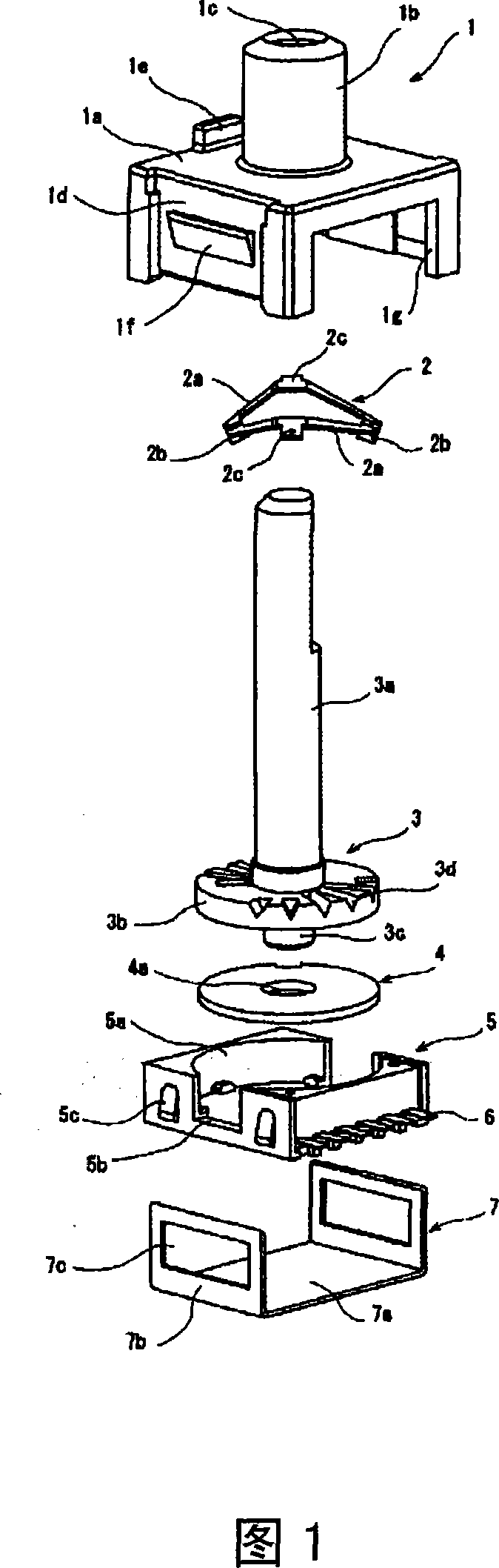
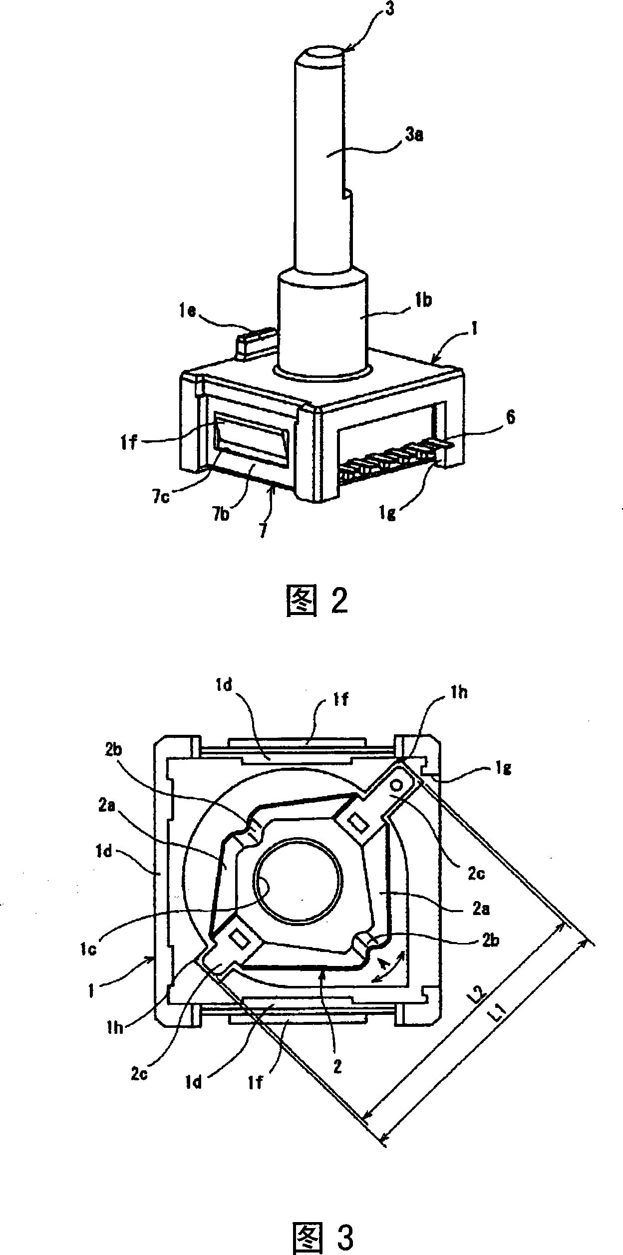
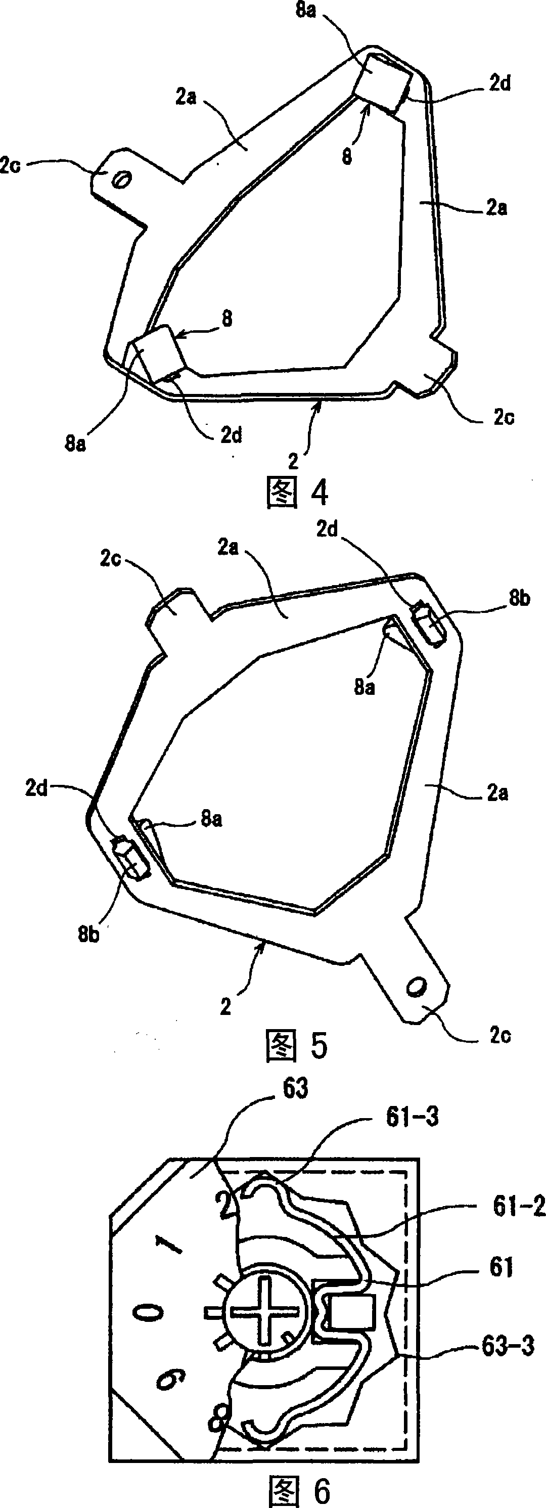
[0034] Hereinafter, FIGS. 1 to 5 show embodiments of the present invention. Fig. 1 is an exploded perspective view showing the rotary electric component of the present invention, Fig. 2 is an assembled perspective view showing the rotary electric component of the present invention, and Fig. 3 is a loose fitting of the box body and the elastic member showing the rotary electric component of the present invention The bottom view of the state, Fig. 4 is a perspective view showing the loose fitting state of the arm portion of the elastic member and the first cam portion of the present invention, and Fig. 5 is a view of the loose fitting state of the arm portion and the first cam portion of the same elastic member from the lower side. A three-dimensional view of the embedded state.

[0035] In FIGS. 1 to 3, the box body 1 is a box-shaped opening made of insulating materials such as synthetic resins, and has: a flat upper plate portion 1a; The bearing portion 1b of the hole 1c; the...


PUM


Abstract

The invention provides a rotation type electric component which can well integrate when rotation axis is operated, which comprises: box body, which includes bearing part; rotation component, whose operation axis is rotatablely located on the bearing part; elastic component, which is located in the box body, and includes first cam part on the front of elasticity displacement arm part; accidented second cam part, which integrates to the first cam part; conductor plate, which comprises first conductive part to integrate to the rotation component, and incidentally rotates with the rotation component; and shell body, which includes second conductive part sliding connects to the conductor plate to output electric signals. When the operation axis rotates, the first cam part integrating to the accidented second cam part is designed to displaces in the rotation direction of the rotation component.

Description

technical field [0001] The present invention relates to a rotary electric component used in various electric equipments and used for switching various modes by rotary operation, and particularly relates to a ratchet mechanism that produces a "click" feeling during rotary operation. Background technique [0002] As the structure of a conventional rotary electric component, the following structure is known, including: a base; a rotor rotatably accommodated in the base; an operation shaft (cylindrical portion) for rotating the rotor; and an opening covering the base. The housing; by rotating the operating shaft, the rotor is rotated, and the movable contact plate provided on the rotor slides on the fixed tab provided on the base, thereby outputting a desired signal (for example, refer to Patent Document 1). [0003] 6 and 7 show the structure of such a conventional rotary electric component. Fig. 6 is a cutaway plan view of main parts of a conventional rotary electric componen...

Claims


Application Information

Patent Timeline
Patent Type & Authority Applications(China)
IPC IPC(8): H01H19/02H01H19/10
CPCH01H19/11
Inventor 林真人
Owner ALPS ALPINE CO LTD
Why Eureka
Try Eureka