Particle field total-field measurement process and apparatus based on laser sheet optical image-forming

A technology of laser sheet light and particle field, applied in measurement devices, instruments, etc., to avoid technical and financial problems, avoid analysis and requirements of followability and light scattering, and avoid interference problems

Inactive Publication Date: 2003-12-31
UNIV OF SCI & TECH OF CHINA
View PDF0 Cites 52 Cited by
  • Summary
  • Abstract
  • Description
  • Claims
  • Application Information

AI Technical Summary

Problems solved by technology

[0004] The present invention proposes a flow field multi-parameter full-field measurement method and its measurement device based on laser sheet light imaging and digital image analysis and processing to solve the shortcomings of the existing single-point measurement technology, and DPIV and SPIV technology in the flow field measurement The limitation that only the velocity of the flow field can be obtained in

Method used


Image

  • Particle field total-field measurement process and apparatus based on laser sheet optical image-forming
  • Particle field total-field measurement process and apparatus based on laser sheet optical image-forming
  • Particle field total-field measurement process and apparatus based on laser sheet optical image-forming

Examples


Embodiment 1

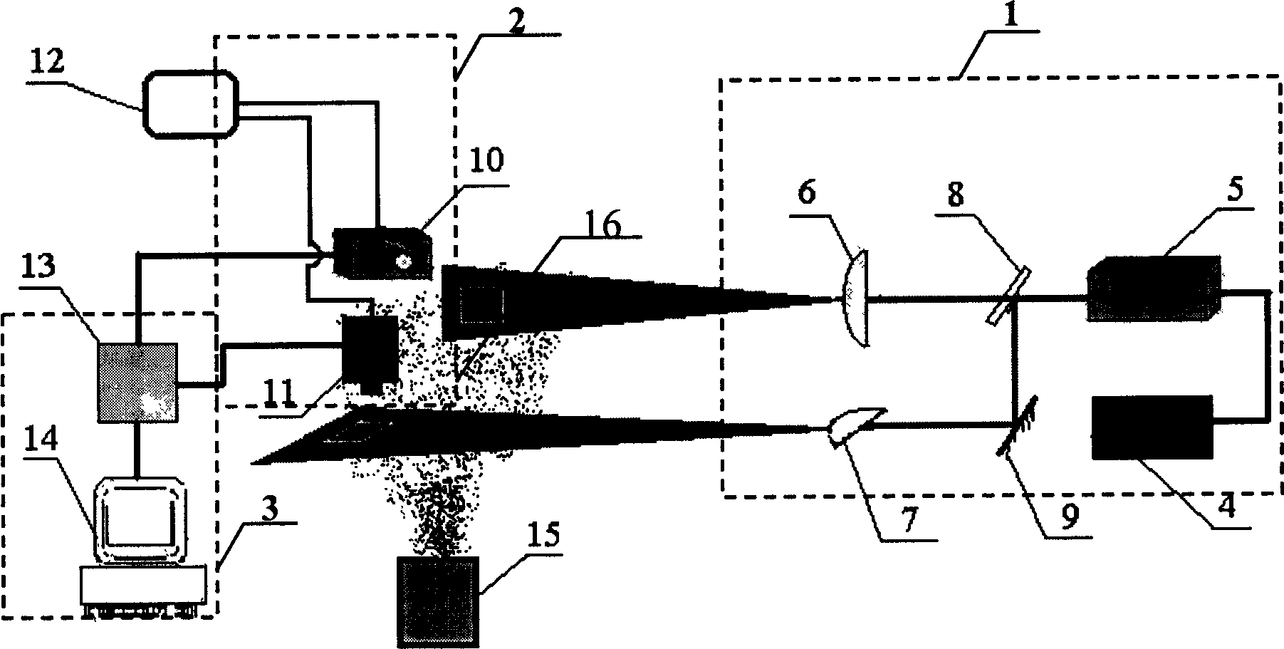
[0016] Embodiment 1: Measurement of particle size and velocity distribution of solid particles in two-phase flow field

[0017] In the present embodiment, the laser sheet optical system 1 is made up of a laser power supply 4, a semiconductor laser 5 with a wavelength of 650nm, two cylindrical lenses 6 and 7, a beam splitter 8 and a mirror 9, and the beam splitter 8 is placed in the laser 5 At about 200mm on the optical axis of the laser beam splitter 8, the cylindrical lens 6 is placed at about 150mm on the optical axis of the transmitted beam after the laser passes through the beam splitter 8, and the mirror 9 is placed on the optical axis of the split beam after the laser passes through the beam splitter 8. At 250mm, the cylindrical lens 7 is placed at about 250mm on the optical axis of the light beam after the split beam is reflected by the reflector 9; the digital imaging system 2 adopts two CCD cameras 10 and 11 with a resolution of 1024×768, wherein the CCD camera 10 Per...

Embodiment 2

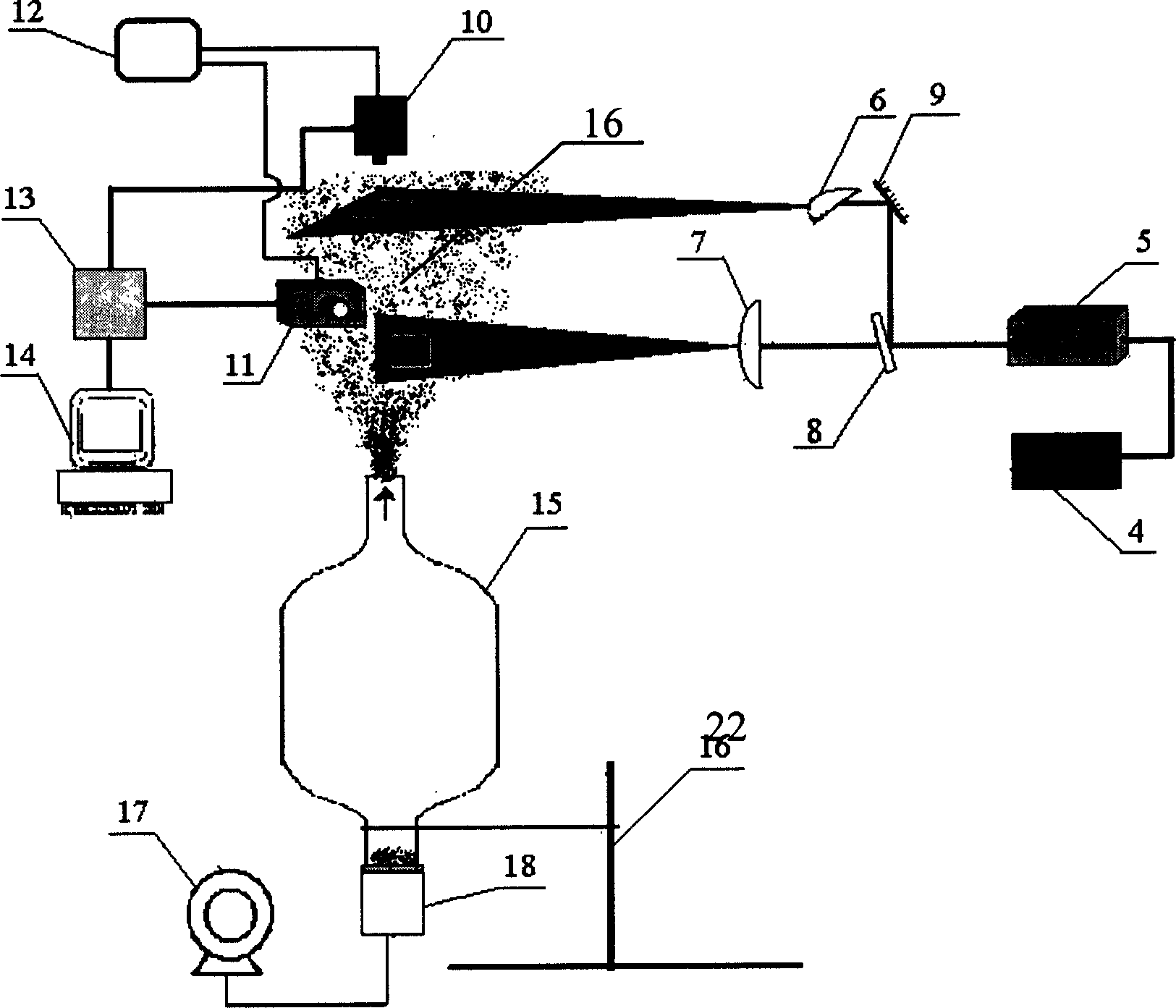
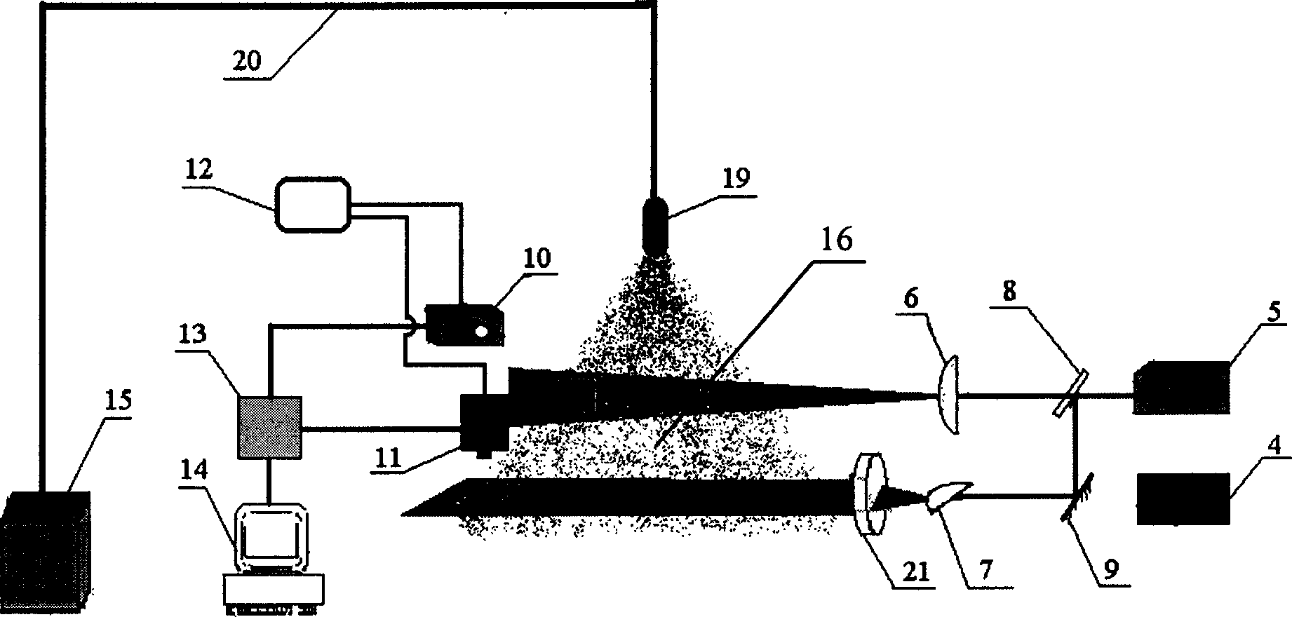
[0021] Embodiment 2: Measurement of the particle size of liquid particles in the gas-liquid two-phase flow field (fine water mist droplet flow field)

[0022] The composition and layout of the measuring device in this embodiment are basically the same as in Embodiment 1, the difference is that in this embodiment the sheet light produced by the cylindrical lens 6 is parallel to the direction of the flow field, while the sheet light produced by the cylindrical lens 7 is vertical In the direction of the flow field; in the present embodiment, a collimator lens 21 with a diameter of 300mm is arranged at about 200mm on the transmission light path of the cylindrical lens 7, and the purpose is to collimate the fan-shaped sheet light into parallel sheet light, so that the laser sheet light The light intensity distribution is as uniform as possible.

[0023] In this embodiment, the two-phase or multi-phase flow field generating device 15 is a combination system of a water storage device...


PUM


Abstract

The present invention is whole particle field measuring method and equipment based on laminar laser imaging and features that particles in test flow field are illuminated with orthogonal laminar laser beams and two CCD cameras are used to take the particle motion locus images both in the direction perpendicular to the flow field and in the direction parallel to the flow field separately. The equivalent diameters of particles are determined via particle image distinction and statistical analysis of covered pixels, and the particle motion speeds, including magnitudes and directions, are determined via the distinction and analysis of particle motion locus image, so as to obtain the size spectrum and speed field distribution of particles in the imaging plane. The present invention needs no addition of tracing particle, and may be used widely in the two-phase and multi-phase flow field measurement in various fields.

Description

Technical field: [0001] The invention relates to a method and device for measuring particle size and velocity in two-phase or multiphase flow. Background technique: [0002] Proceedings of the 15th International Conference on Fire Safety Research (15th meeting of the UJNR panel on fire research and safety, March 1-7, 2000, pp.471-481.) and Proceedings of the 8th International Conference on Liquid and Spray Systems (8thInternational Conference on Liquid and Spray Systems, Pasadena, USA, 2000, 886-892.) pointed out that although the Digital Particle Image Velocimetry (DPIV) method developed in recent years can do dynamic full-field measurement of the flow field , but because it uses the particle image cross-correlation technique to reconstruct the velocity of the flow field, it is required that the laser sheet light must be parallel to the direction of the flow field, and it is required to apply tracer particles with good followability and light scattering characteristics to t...

Claims


Application Information

Patent Timeline
Patent Type & Authority Applications(China)
IPC IPC(8): G01D21/02
Inventor 王喜世廖光煊秦俊范维澄伍小平
Owner UNIV OF SCI & TECH OF CHINA
Why Eureka
Try Eureka