

Interference type optical fiber gyroscope based on MZ interference principle
A fiber optic gyroscope and interferometric technology, which is applied to steering sensing equipment and other directions, can solve problems such as low optical power utilization, low signal-to-noise ratio, and interference, and achieve the effects of high cost performance, high sensitivity, and stable performance
- Summary
- Abstract
- Description
- Claims
- Application Information
AI Technical Summary
Problems solved by technology
Method used
Image

Examples
Embodiment Construction
[0044] specific implementation
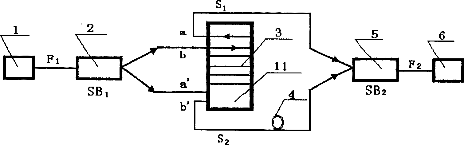
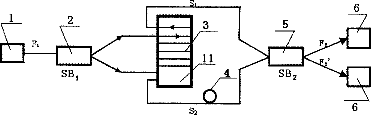
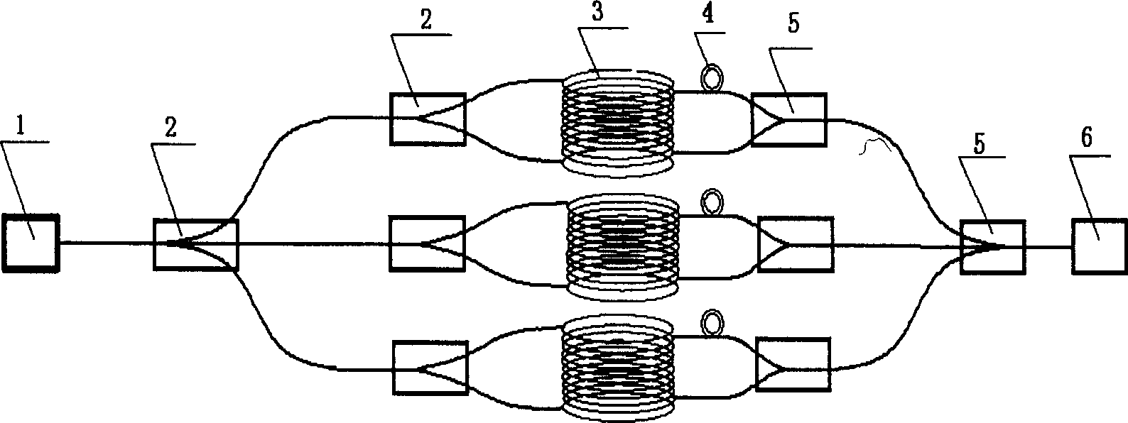
[0045] refer to figure 1 , is a schematic structural diagram of a single-axis MZ interferometric fiber optic gyroscope according to an embodiment of the present invention. The present invention adopts the principle of M-Z interference with two-arm symmetrical ring optical fiber (non-resonant type), which is completely different from the principle of Sagnac interference type fiber optic gyroscope and resonant type fiber optic gyroscope. Laser light 1 with a wavelength of 0.8 μm to 1.6 μm emitted from the LD semiconductor laser enters the single-mode fiber F 1 After being 3db beam splitter 2SB 1 After splitting, the beams are sent to two optical fiber signal arms S with exactly the same length 1 Ports 1, 1' and S 2 In ports 2 and 2′, the two optical fiber signal arms are wound into an optical fiber coil 3 with the same center of circle and the same diameter D in the same winding method, and the optical signals are respectively transmitted fr...
PUM
 Abstract
Description
Claims
Application Information