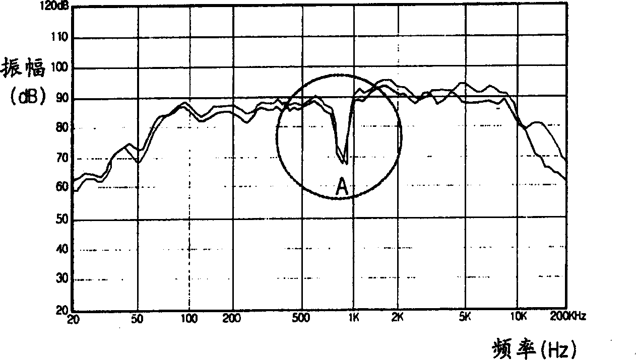
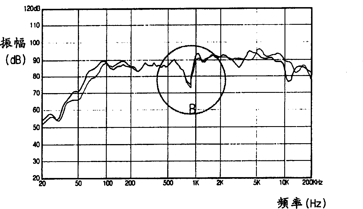
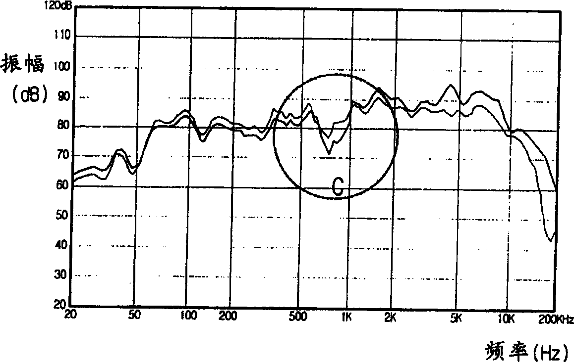
Vibrating diaphragm edgefold of loudspeaker

A loudspeaker and peripheral technology, applied in the direction of loudspeaker diaphragm material, loudspeaker diaphragm shape, non-planar diaphragm/paper cone, etc., can solve problems such as deterioration of sound sensitivity

Inactive Publication Date: 2004-09-22
李钟表
View PDF0 Cites 2 Cited by
  • Summary
  • Abstract
  • Description
  • Claims
  • Application Information

AI Technical Summary

Problems solved by technology

Deterioration of sound sensitivity when the shape of the diaphragm fold is deformed and cannot return to its original shape

Method used


Image

  • Vibrating diaphragm edgefold of loudspeaker
  • Vibrating diaphragm edgefold of loudspeaker
  • Vibrating diaphragm edgefold of loudspeaker

Examples


Embodiment Construction

[0033] Figure 3A , 3B and 3C are perspective, plan and side views, respectively, of a diaphragm with a diaphragm flange attached thereon according to the first preferred embodiment of the present invention. exist Figure 3A to Figure 3C In , reference numerals 31 and 32 denote a diaphragm flange and a diaphragm, respectively. The diaphragm flange 31 is composed of a first adhesive portion 311 a , a second adhesive portion 311 b and a rolled portion 312 . Although Figure 3A to Figure 3C The diaphragm hem 31 of the speaker shown in has an upper rolled shape, but this is only an example, and other than the upper rolled shape, such as a lower rolled shape, an N-shaped rolled shape, an M-shaped rolled shape, etc. can be used. Various shapes of raised shape and W-shaped rolled shape. Figure 4 Shows when the roll of the diaphragm hem is an upper roll (a), a lower roll (b), an N-shaped roll (c), an M-shaped roll (d) and a W-shaped roll (e) Sectional view of the diaphragm flan...


PUM


Abstract

Provided is a diaphragm edge of a speaker which is formed by compressing a material including silicon rubber and has an emboss portion on a front surface thereof so that sensitivity of sound is improved. Also, a diaphragm edge of a speaker is formed by compressing a material including silicon rubber and powdered viscose rayon and has an emboss on a front surface thereof.

Description

technical field [0001] The present invention relates to a diaphragm flange for a loudspeaker, and more particularly to a diaphragm flange for a speaker formed by pressing a material containing silicone rubber and having embossed portions on its front surface in order to enhance sound sensitivity. Background technique [0002] The diaphragm flange of a loudspeaker has two main functions. One function is to respond smoothly to the movement of the vibratory system and the various parts of the drive system, while at the same time precisely maintaining the position of the diaphragm by preventing it from moving laterally. Another function is to prevent sound waves radiated from the diaphragm toward its front side from being mixed with and canceled out with sound waves radiated toward its rear side having an opposite phase. [0003] The amplitude of the diaphragm is inversely proportional to the square of the frequency. Because of this, since greater amplitudes occur in the bass...

Claims


Application Information

Patent Timeline
Patent Type & Authority Applications(China)
IPC IPC(8): H04R7/22H04R7/02H04R7/18H04R7/20
CPCH04R7/18H04R2307/207H04R2307/204H04R7/02H04R7/20
Inventor 李钟表
Owner 李钟表
Why Eureka
Try Eureka