Electric clipper with oil pad

A haircut pusher and oil channel technology, which is applied in metal processing and other directions, can solve the problems of inconvenience, shortening, and unreachable service life of hair clippers

Inactive Publication Date: 2004-12-08
吴泰准
View PDF0 Cites 2 Cited by
  • Summary
  • Abstract
  • Description
  • Claims
  • Application Information

AI Technical Summary

Problems solved by technology

[0004] However, it is inconvenient since the clipper must be lubricated each time it is used
Also, since it often happens that the hair clippers are used without lubrication, the service life of the hair clippers is not achieved, but shortened

Method used


Image

  • Electric clipper with oil pad
  • Electric clipper with oil pad
  • Electric clipper with oil pad

Examples


Embodiment Construction

[0011] Reference will now be made in detail to a preferred embodiment of the invention which is illustrated in the accompanying drawings. Wherever possible, the same reference numbers will be used in the drawings and throughout the specification to refer to the same or like parts.

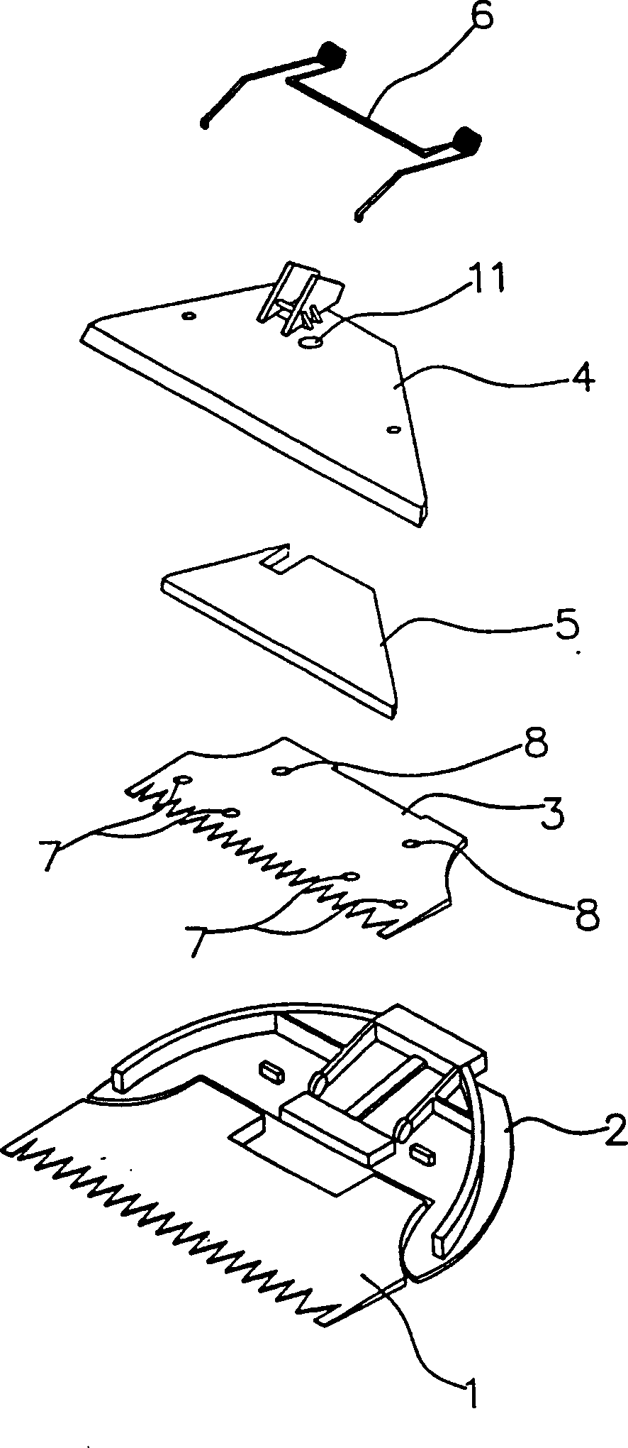
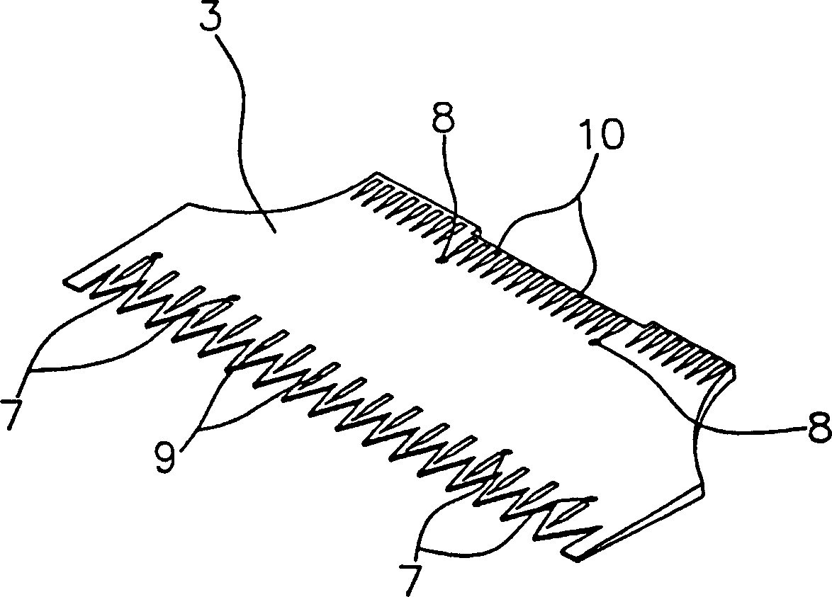
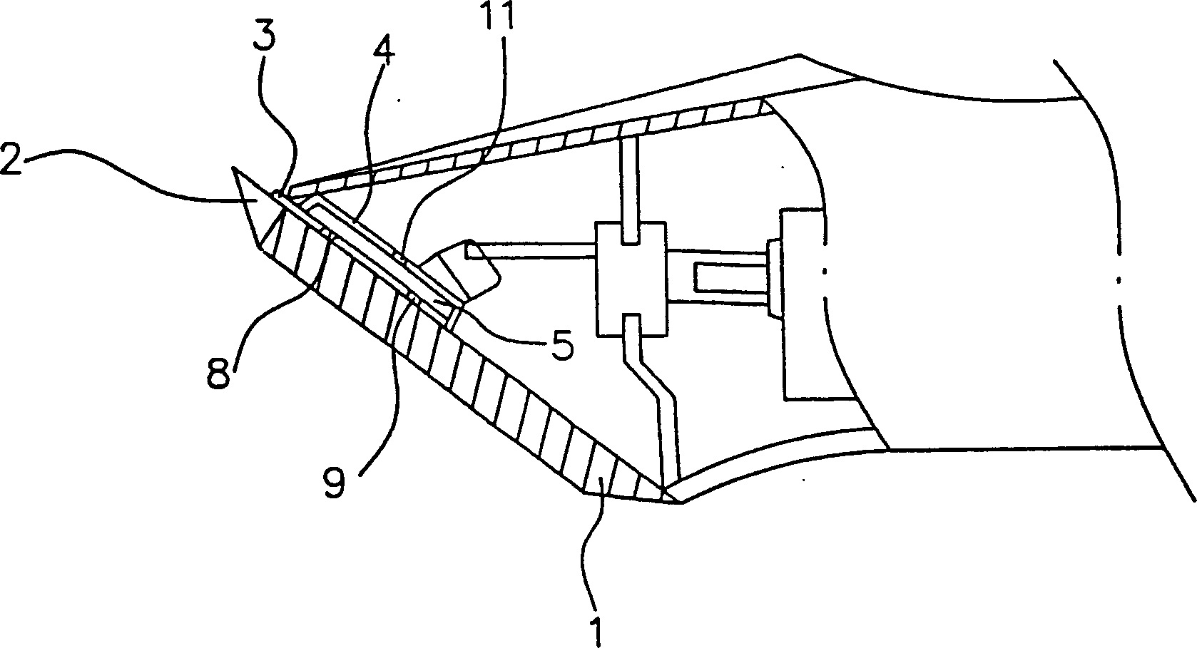
[0012] figure 1 is an exploded perspective view showing a hair clipper with an oil pad according to an embodiment of the present invention. The hair clipper according to the invention comprises a fixed clipper blade 1 and a movable clipper blade 3 . The fixed clipper blade 1 is fixed on the main body 2 of the clipper head. The movable clipper blade 3 is arranged on the fixed clipper blade 1 .

[0013] The movable clipper blade 3 is connected to a guide bracket 4, so that when the guide bracket 4 reciprocates left and right by an eccentric cam driven by a motor (not shown), the movable clipper blade 3 can follow the The guide brackets 4 move together.

[0014] A receiving groove is provided on ...


PUM


Abstract

A receiving groove is defined on a lower surface of a guide bracket. An oil pad is received in the groove. The guide bracket is defined adjacent to an end thereof with an oil inlet hole. A movable clipper blade is defined adjacent to front and rear ends thereof with front and rear oil passages and is positioned underneath the oil pad, such that the front and rear oil passages are communicated with oil storing grooves defined on a lower surface of the movable clipper blade, to supply oil between the movable clipper blade and a fixed clipper blade.

Description

technical field [0001] The present invention relates to a hair clipper with an oil pad for supplying oil to a movable clipper blade reciprocating left and right on a fixed clipper blade. Background technique [0002] Usually, in hair clippers, a fixed clipper blade is fixed on the body of the clipper head, and a movable clipper blade is arranged on the fixed clipper blade. As the movable clipper blades reciprocate left and right under the drive of the motor, the hair is cut. [0003] In order to ensure that the fixed clipper blades and the movable clipper blades cut hair properly, the hair clippers are used with a lubricant supplied between the fixed and movable clipper blades. [0004] However, since the hair clipper must be lubricated every time it is used, it is inconvenient. And, since it often happens that the hair clippers are used without lubrication, the service life of the hair clippers cannot be reached, but shortened instead. Contents of the invention [0005...

Claims


Application Information

Patent Timeline
Patent Type & Authority Applications(China)
IPC IPC(8): B26B19/40
CPCB26B19/40
Inventor 吴泰准
Owner 吴泰准
Why Eureka
Try Eureka