

Measuring device for clamping holding force
A test device, force sensor technology, applied in the direction of measuring devices, force/torque/work measuring instruments, measuring force components, etc.
- Summary
- Abstract
- Description
- Claims
- Application Information
AI Technical Summary
Problems solved by technology
Method used
Image

Examples
Embodiment approach 1
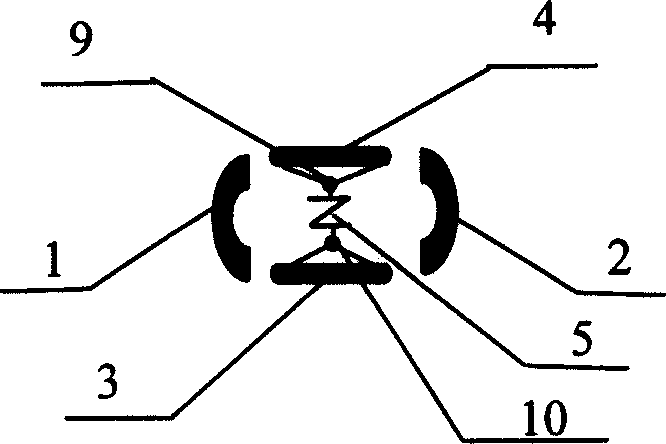
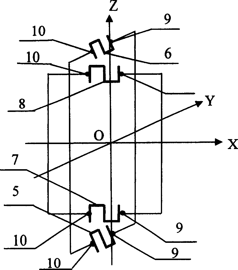
[0014] First, connect two arc-shaped cylindrical shells 1, 2 and two rectangular spring steel plates 3, 4, leaving a gap of 15 cm between them to meet the maximum measuring range, and four force sensors 5, 6 inside. , 7, 8, and each sensor has two force-transmitting steel balls 9, 10; inside the clamping force test device are two mutually perpendicular two-dimensional force-measuring frame structures, and each frame is equipped with two movable The force sensors 5, 6, 7, 8 that measure the clamping force in different directions and can determine the position of the force acting point, all the forces are transmitted to the sensors 5, 6, 7, ), one end of the force transmission steel ball 9, 10 is respectively connected to the force sensor 5, 6, 7, 8, and the other end is respectively connected to two arc-shaped cylindrical shells 1, 2 and two rectangular spring steel plates 3 , 4 above; the outer surface is wrapped with a layer of 15cm thick elastic sponge, and then wrapped with...
Embodiment approach 2
[0016] First of all, connect two shells 1, 2 in the form of circular arc columns with two rectangular spring steel plates 3, 4, leaving a gap of 20 cm between them to meet the maximum measuring range, inside which there are four force sensors 5, 6 , 7, 8, and each sensor has two force-transmitting steel balls 9, 10; inside the clamping force test device are two mutually perpendicular two-dimensional force-measuring frame structures, and each frame is equipped with two movable The force sensors 5, 6, 7, 8 that measure the clamping force in different directions and can determine the position of the force acting point, all the forces are transmitted to the sensors 5, 6, 7, 8, one end of the force transmission steel ball 9, 10 is respectively connected to the force sensor 5, 6, 7, 8, and the other end is respectively connected to two circular arc columnar shells 1, 2 and two rectangular spring steel plates 3 , 4 above; the outer surface is wrapped with a layer of 20cm thick elasti...
Embodiment approach 3
[0018] First of all, connect two shells 1, 2 in the form of circular arc columns with two rectangular spring steel plates 3, 4, and leave a gap of 18 cm between them to meet the maximum measuring range, and there are four force sensors 5, 6 inside. , 7, 8, and each sensor has two force-transmitting steel balls 9, 10; inside the clamping force test device are two mutually perpendicular two-dimensional force-measuring frame structures, and each frame is equipped with two movable The force sensors 5, 6, 7, 8 that measure the clamping force in different directions and can determine the position of the force acting point, all the forces are transmitted to the sensors 5, 6, 7, 8, one end of the force transmission steel ball 9, 10 is respectively connected to the force sensor 5, 6, 7, 8, and the other end is respectively connected to two circular arc columnar shells 1, 2 and two rectangular spring steel plates 3 , 4 above; the outer surface is wrapped with a layer of 18cm thick elast...
PUM
| Property | Measurement | Unit |
|---|---|---|
| thickness | aaaaa | aaaaa |
Abstract
Description
Claims
Application Information