
Curve saw
A technology of jig saw and saw blade, applied in the field of jig saw, can solve problems such as complicated operation
- Summary
- Abstract
- Description
- Claims
- Application Information
AI Technical Summary
Problems solved by technology
Method used
Image

Examples
Embodiment Construction
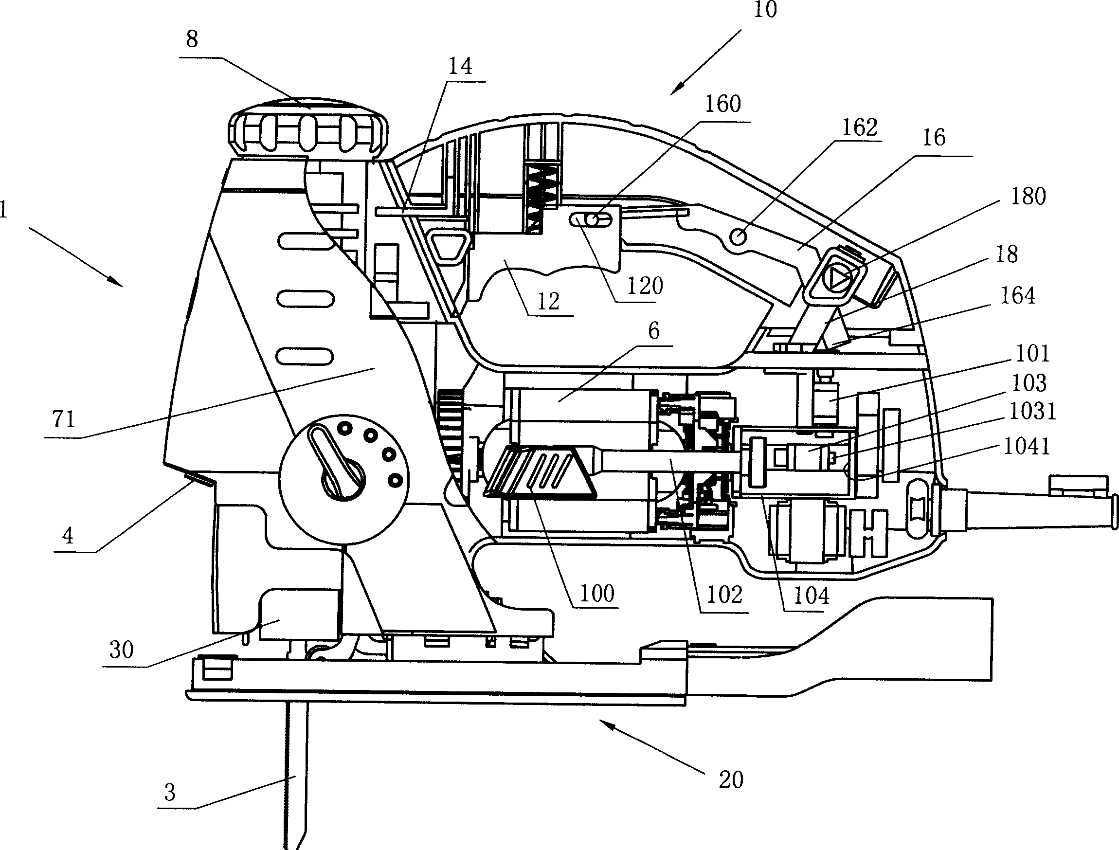
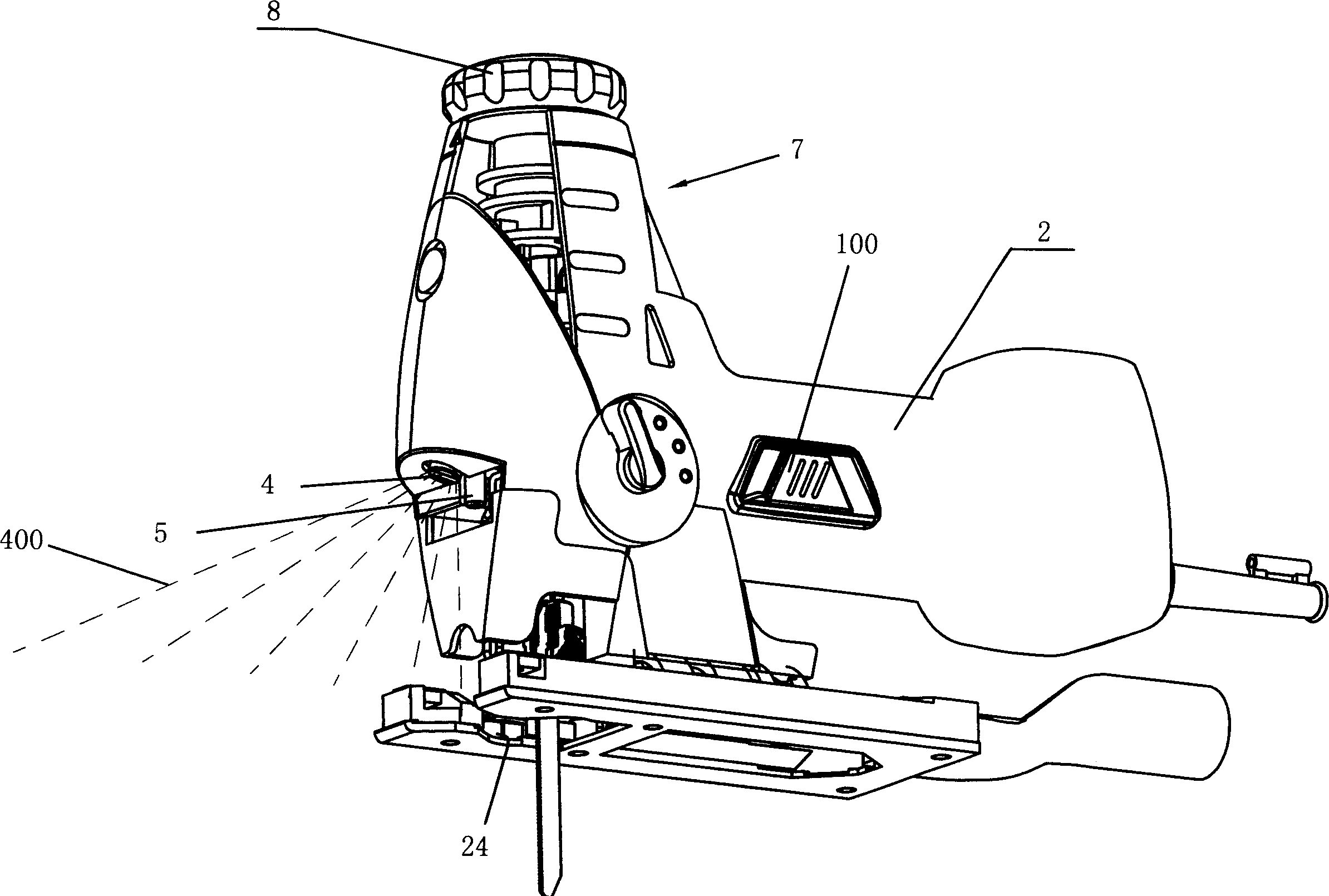
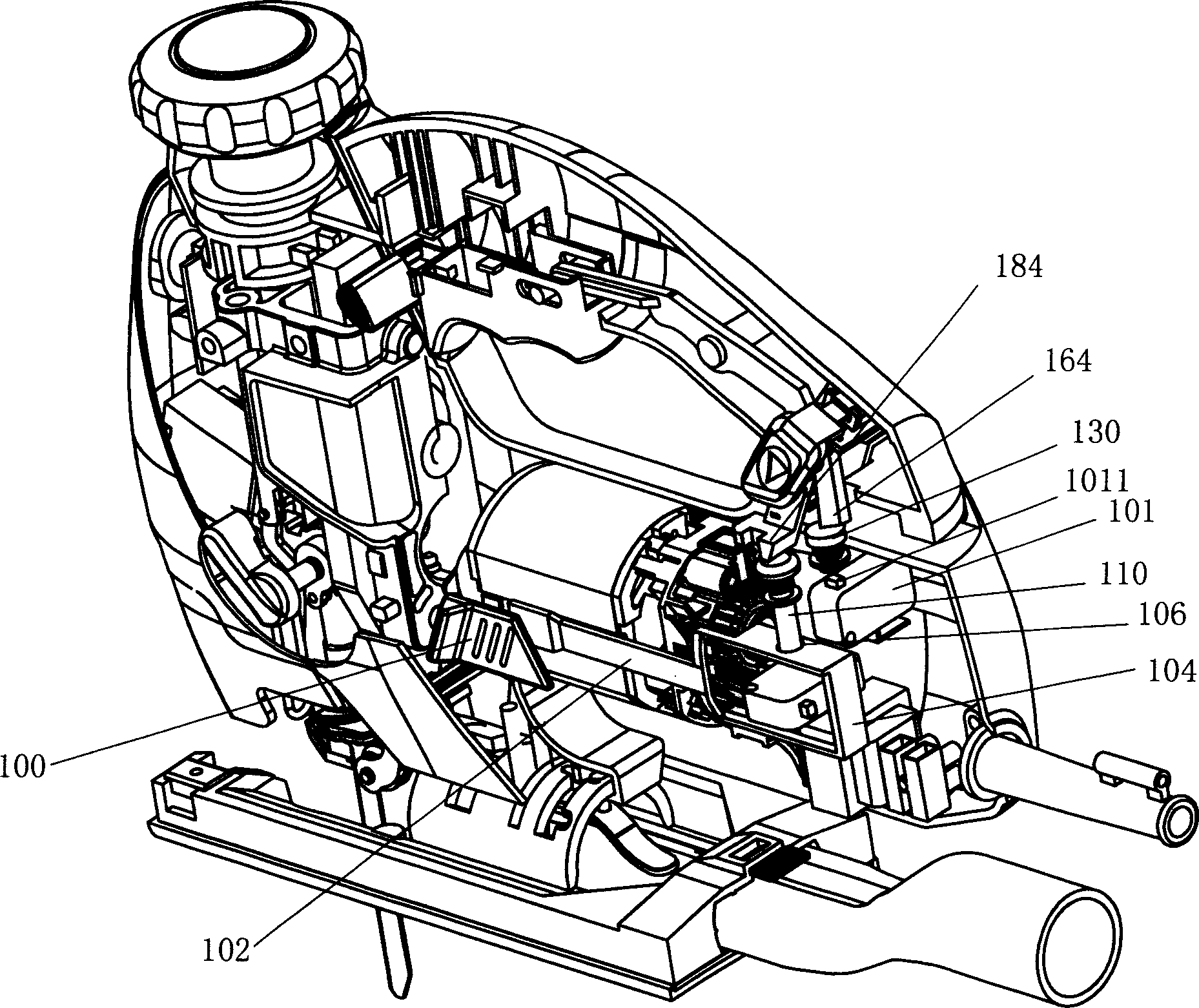
[0031] Such as figure 1 and figure 2 As shown, the jigsaw 1 of the present invention includes a front body 7, a main body 2, a motor 6 located in the main body 2, a first switch 103, a saw blade 3 for cutting, and a saw blade 3 located in the front body. A mechanical transmission device 71 (not shown) for converting the rotary motion of the motor 6 into the reciprocating motion of the saw blade 3, a detachable handle 10, laser marking device 4, lighting device 5, saw blade clamping device 30, and base plate 20.
[0032] First, the attachment and detachment of the handle will be described. As shown in Figure 4, the front end of the handle 10 has an insert 14 for positioning the position of the handle. There is a hole 140 on the front body 7 to match the insert 14. Insert the insert 14 into the hole 140, and the two can be closely matched. Thereby the position of one end of the handle 10 on the front body 7 is determined. A pair of connecting devices 18 are arranged at the ...
PUM
 Abstract
Description
Claims
Application Information