
Image encoding method, device thereof, and control program thereof

一种图像编码、控制程序的技术,应用在图像通信、电视、电气元件等方向,能够解决量化、不显示统一的分布、无法执行预测性能的等问题,达到精细量化、减少代码量的效果

Inactive Publication Date: 2007-02-28
NEC CORP
View PDF1 Cites 2 Cited by
  • Summary
  • Abstract
  • Description
  • Claims
  • Application Information

AI Technical Summary

Problems solved by technology

[0017] The first problem is that the individual blocks that make up the MB do not necessarily have the same pattern
In this case, the prior art cannot perform quantization suitable for the pattern of each block constituting the MB
[0018] The second problem is the performance of minimizing the prediction error (hereinafter called predictive performance) differs for each block that makes up the MB
In this case, the prior art cannot perform quantization suitable for the predictive performance of each block composing the MB
[0019] The third problem is that the distribution of the orthogonal transform coefficients corresponding to the coordinates in the block (hereinafter referred to as spatial frequency) varies due to the first and second reasons, and the individual blocks constituting the MB do not show a uniform distributed
In this case, the prior art cannot perform quantization suitable for the distribution of orthogonal transform coefficients for each block

Method used


Image

  • Image encoding method, device thereof, and control program thereof
  • Image encoding method, device thereof, and control program thereof
  • Image encoding method, device thereof, and control program thereof

Examples


no. 1 example

[0059] Next, a first embodiment of the present invention will be described.

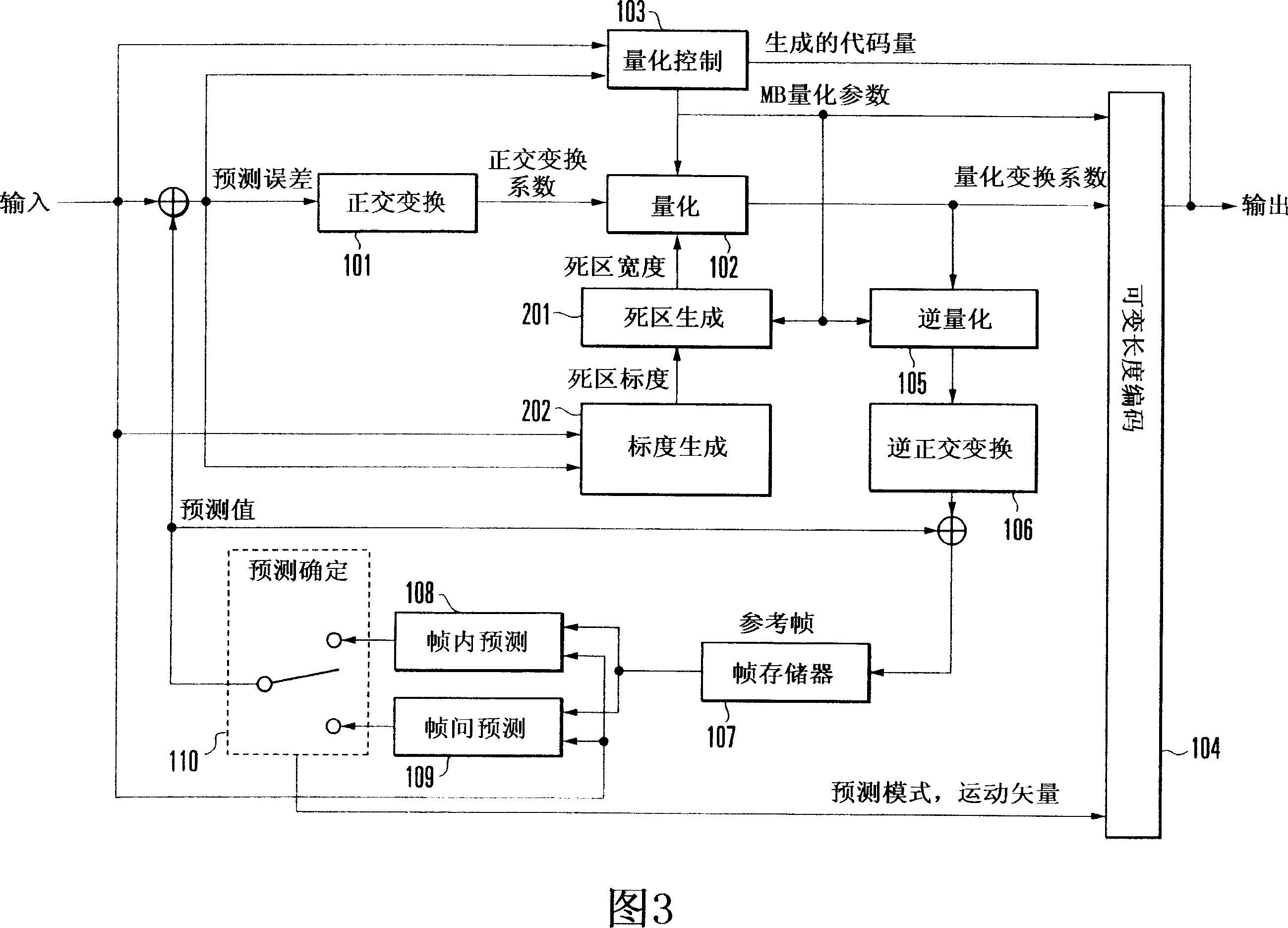
[0060] Fig. 3 shows an example of the structure of the first embodiment.

[0061] In this embodiment, an image frame forming a moving image is divided into a plurality of regions called macroblocks (MBs), and each block obtained by further dividing each MB is encoded.

[0062] From the above MB, the prediction value provided by the intra prediction device 108 that performs prediction from the same image frame reconstructed in the past or the inter prediction device 109 that performs prediction from a past image frame reconstructed in the past is extracted . The MB signal from which the predicted value has been extracted is called a prediction error signal.

[0063] The prediction error signal described above is divided into smaller blocks (hereinafter simply referred to as blocks), and each block is transformed from the spatial domain to the frequency domain by the orthogonal transform device 101 ....

no. 2 example

[0156] Next, a second embodiment of the present invention will be described.

[0157] Fig. 11 shows the structure of the second embodiment of the present invention. The structure of the second embodiment includes a spatial frequency dead zone scale generator 203 instead of the block dead zone scale generator 202 in the structure of the first embodiment. The spatial frequency dead zone scale generator 203 will correspond to the dead zone scale dz_scale(b, i, j) (0≤b≤15, 0≤i≤3, 0≤j≤3) are supplied to the dead zone generator 201.

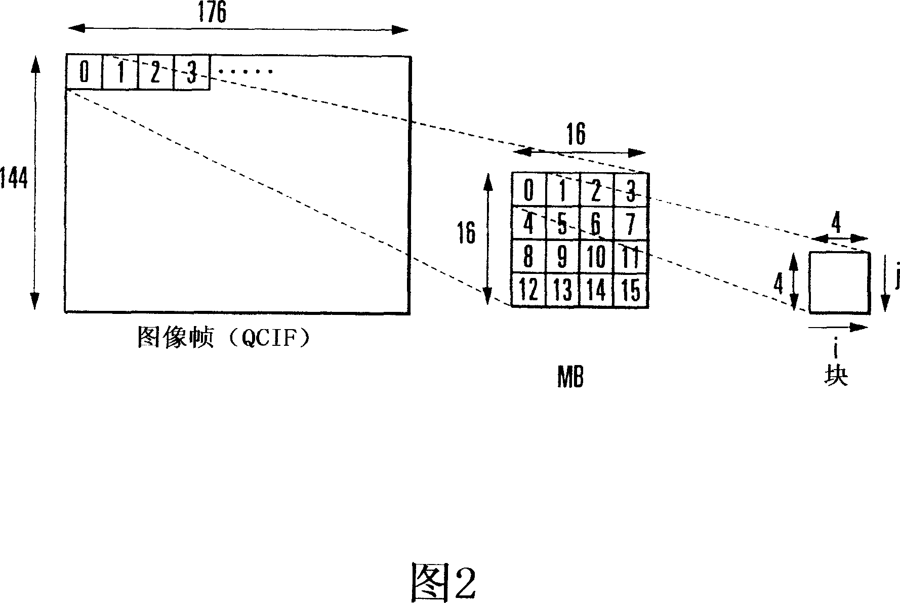
[0158] To explain more concretely, it is assumed that in the following description, the size of an image frame is a QCIF (176×144) size, the size of an MB is a 16×16 size, and the size of a block is a 4×4 size. Obviously, the invention is also applicable where other dimensions are used.

[0159] Next, the spatial frequency dead zone scale generator 203, which is a typical feature of the second embodiment, will be described. Note that a detailed des...

no. 3 example

[0210] Next, a third embodiment of the present invention will be described.

[0211] Fig. 16 shows the structure of a third embodiment of the present invention. The structure of the third embodiment includes a hybrid dead zone scale generator 204 in place of the block dead zone scale generator 202 in the structure of the first embodiment. The spatial frequency dead zone scale generator 203 will correspond to the dead zone scale dz_scale(b, i, j) (0≤b≤15, 0≤i≤3, 0≤j≤3) are supplied to the dead zone generator 201.

[0212] To explain more concretely, it is assumed that in the following description, the image frame size is QCIF (176×144) size, the size of MB is 16×16 size, and the size of blocks forming MB is 4×4 size. Obviously, the invention is also applicable where other dimensions are used.

[0213] Furthermore, the hybrid dead zone scale generator 204, which is a typical feature of the third embodiment, will be described below. Note that a detailed description of the sam...


PUM


Abstract

A block dead zone scale generator (202) receives an image signal and a prediction error, analyzes the pattern or prediction performance of a target block, and outputs a dead zone scale suitable for the pattern or prediction performance of the block. A dead zone generator (201) receives a dead zone scale from the block dead zone scale generator (202) and an MB quantization parameter from a quantization control device (103), calculates a dead zone width from the zone scale and the MB quantization parameter, and outputs the dead zone width. A quantization device (102) quantizes an orthogonal transformation coefficient supplied from an orthogonal transformation device (101) by using a dead zone from the dead zone generator (201), and outputs a quantized transformation coefficient. This makes it possible to realize quantization with arbitrary strength for each transformation coefficient and for each block comprising a plurality of transformation coefficients as constituent elements, thereby providing a high-quality image encoding technology.

Description

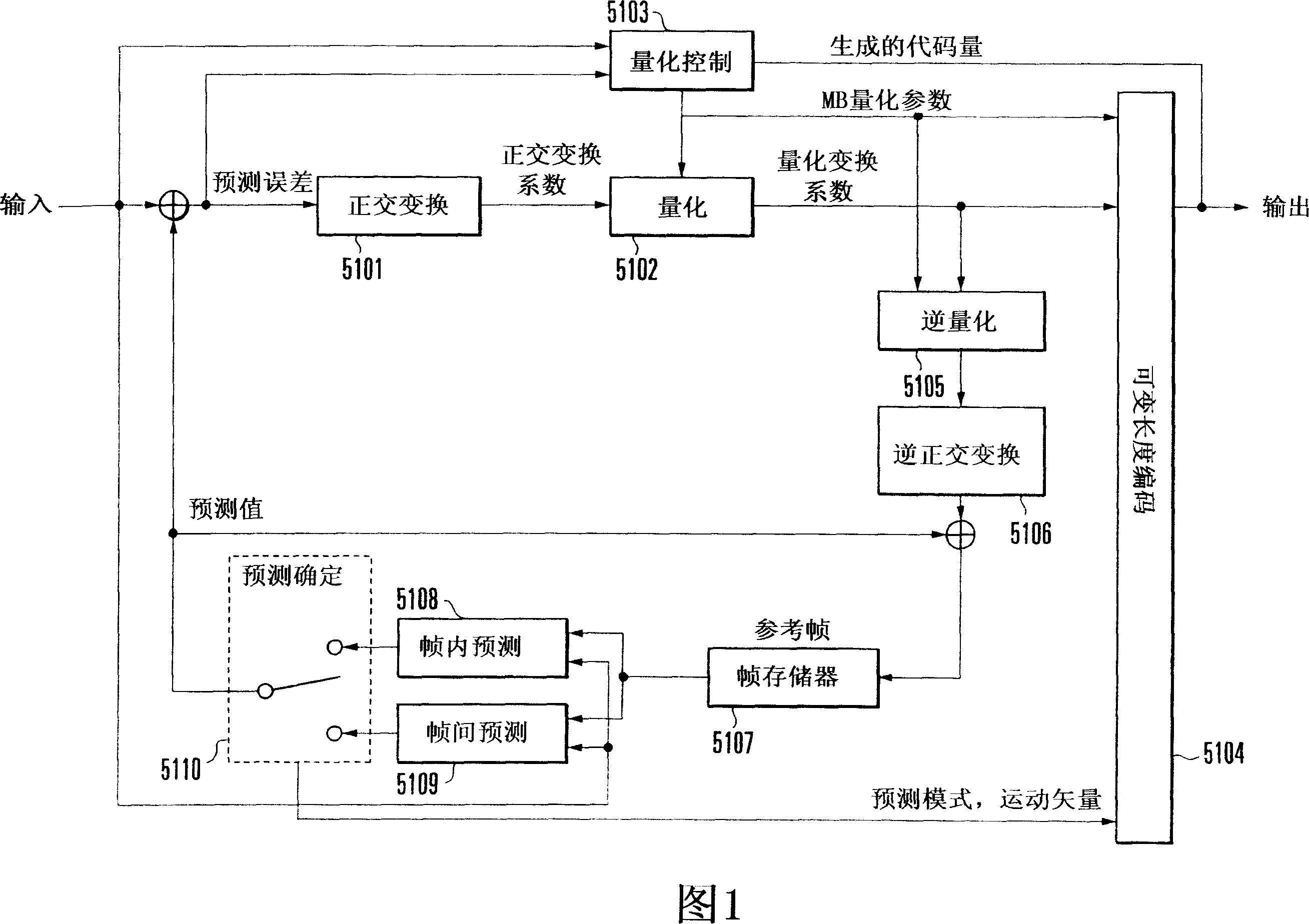
technical field [0001] The present invention relates to an image encoding method, an apparatus thereof, and a control program thereof, and particularly to an image encoding method performing adaptive quantization for improving subjective image quality, an apparatus thereof, and a control program thereof. Background technique [0002] The prior art will be described below with reference to the accompanying drawings. [0003] First, hybrid moving image coding as a prior art based on an orthogonal transform device and a prediction (intra prediction / inter prediction) device will be described with reference to FIG. 1 . [0004] According to the related art, an image frame forming a moving image is divided into a plurality of regions called macroblocks (MBs), and each block obtained by further dividing each MB is encoded. FIG. 2 shows the structure of an AVC (Advanced Video Coding: ISO / IEC 14496-10) image frame as a specific example of the image frame structure according to the p...

Claims


Application Information

Patent Timeline
Patent Type & Authority Applications(China)
IPC IPC(8): H04N7/30H04N19/124H04N19/136H04N19/137H04N19/14H04N19/157H04N19/159H04N19/176H04N19/196H04N19/60
CPCH04N19/00781H04N19/00278H04N7/26164H04N19/00181H04N19/00193H04N19/00096H04N19/00139H04N19/00024H04N19/105H04N19/126H04N19/136H04N19/149H04N19/152H04N19/176H04N19/61H04N19/132H04N19/60
Inventor 蝶野庆一仙田裕三
Owner NEC CORP
Learn More