Emergency information lighting system

An emergency and lighting system technology, applied in the field of lighting systems, can solve the problem of invisible information

Inactive Publication Date: 2007-03-07
AVERY DENNISON CORP
View PDF2 Cites 0 Cited by
  • Summary
  • Abstract
  • Description
  • Claims
  • Application Information

AI Technical Summary

Problems solved by technology

However, said information will not be visible when the original light source is not lit due to its power being disconnected

Method used


Image

  • Emergency information lighting system
  • Emergency information lighting system
  • Emergency information lighting system

Examples


Embodiment Construction

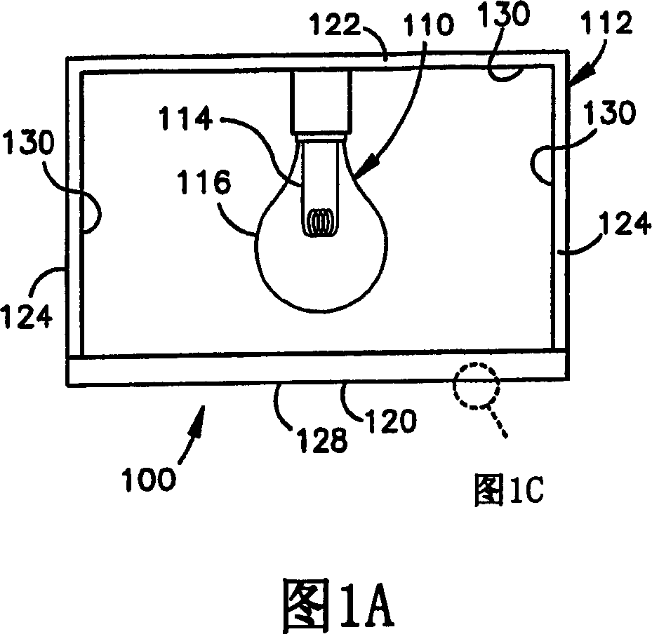
[0029] [0029] Referring now to the drawings, and initially to FIG. 1A, there is shown a lighting system 100 in accordance with the present invention. The lighting system 100 includes an original light source 110 and a box 112 of the original light source 110 . The primary light source 110 includes a powered lighting element 114 . For example, if primary light source 110 is an incandescent light bulb, electronic component 114 may include a filament electrically connected to a power source. If the lighting system 110 includes fluorescent tubes, the electronic components 114 may include a transformer ballast electrically connected to a power source and a fluorescent tube wrapped around the transformer. In either or both cases, primary light source 110 additionally includes a glass or plastic encapsulation 116 (ie, “bulb or tube”) that surrounds lighting element 114 .

[0030] [0030] The box body 112 includes a front wall 120, a rear wall 122 and a side wall 124. The above modif...


PUM


Abstract

An emergency information lighting system (100), comprising a primary light source (110) and a housing (112) for the primary light source (110). The housing (112) includes a first wall (120) with indicia openings (126) which correspond to emergency information. The primary light source (110) emits primary light, which passes through the indica openings (126) to display the emergency information to a viewing environment. The housing (112) or a bulb (116) incorporates a phosphorescent material which, in the absence of the primary light, emits passive light to display the emergency information to the viewing environment.

Description

technical field [0001] [0001] The present invention relates generally to an emergency information lighting system as indicated, and more particularly to a lighting system in which emergency information can be displayed by means of primary light, or in the absence of primary light. The presence of light is shown by emitting phosphorescent passive light. Background technique [0002] [0002] A common emergency information lighting system includes an original light source and a housing for the original light source. A primary light source has electronically powered lighting elements (eg, filaments, transformer ballasts, etc.) and an enclosure (ie, a "bulb") surrounding these lighting elements. The box usually includes a series of barriers, and the front barrier contains indicator holes, which correspond to emergency information. For example, the hole could spell out the word "EXIT" or display an arrow pointing in the proper direction of escape. Commercial offices, factories, ...

Claims


Application Information

Patent Timeline
Patent Type & Authority Applications(China)
IPC IPC(8): G09F13/20
Inventor M·E·汉宁顿
Owner AVERY DENNISON CORP
Why Eureka
Try Eureka