Impact energy absorbing device for a vehicle

a technology for absorbing devices and vehicles, applied in vehicle safety arrangments, bumpers, transportation and packaging, etc., can solve the problems of less effective energy absorption, achieve the effect of encouraging crushing as opposed to bending or buckling, and thin cell walls

Inactive Publication Date: 2018-11-06
JAGUAR LAND ROVER LTD
View PDF8 Cites 70 Cited by
  • Summary
  • Abstract
  • Description
  • Claims
  • Application Information

AI Technical Summary

Benefits of technology

[0009]Each cell may include a mouth portion that is configured to encourage the cell to initially crush inwardly, towards its centre. The mouth portion may have an inverse taper. This advantageously encourages the cells to deform in the most effective way for absorbing energy.
[0017]According to one embodiment, at least one of the cells is configured to cooperate with an attachment structure provided on a frame of the vehicle to mount the device to the frame. The at least one cell may protrude from the mounting region and is received by the attachment structure. These embodiments advantageously allow the device to be easily mounted onto a vehicle.

Problems solved by technology

However, even at small angles of inclination the crash box may bend or buckle about the longitudinal axis rather than crush and collapse along its longitudinal axis, making it less effective at absorbing energy.

Method used


Image

  • Impact energy absorbing device for a vehicle
  • Impact energy absorbing device for a vehicle
  • Impact energy absorbing device for a vehicle

Examples


Embodiment Construction

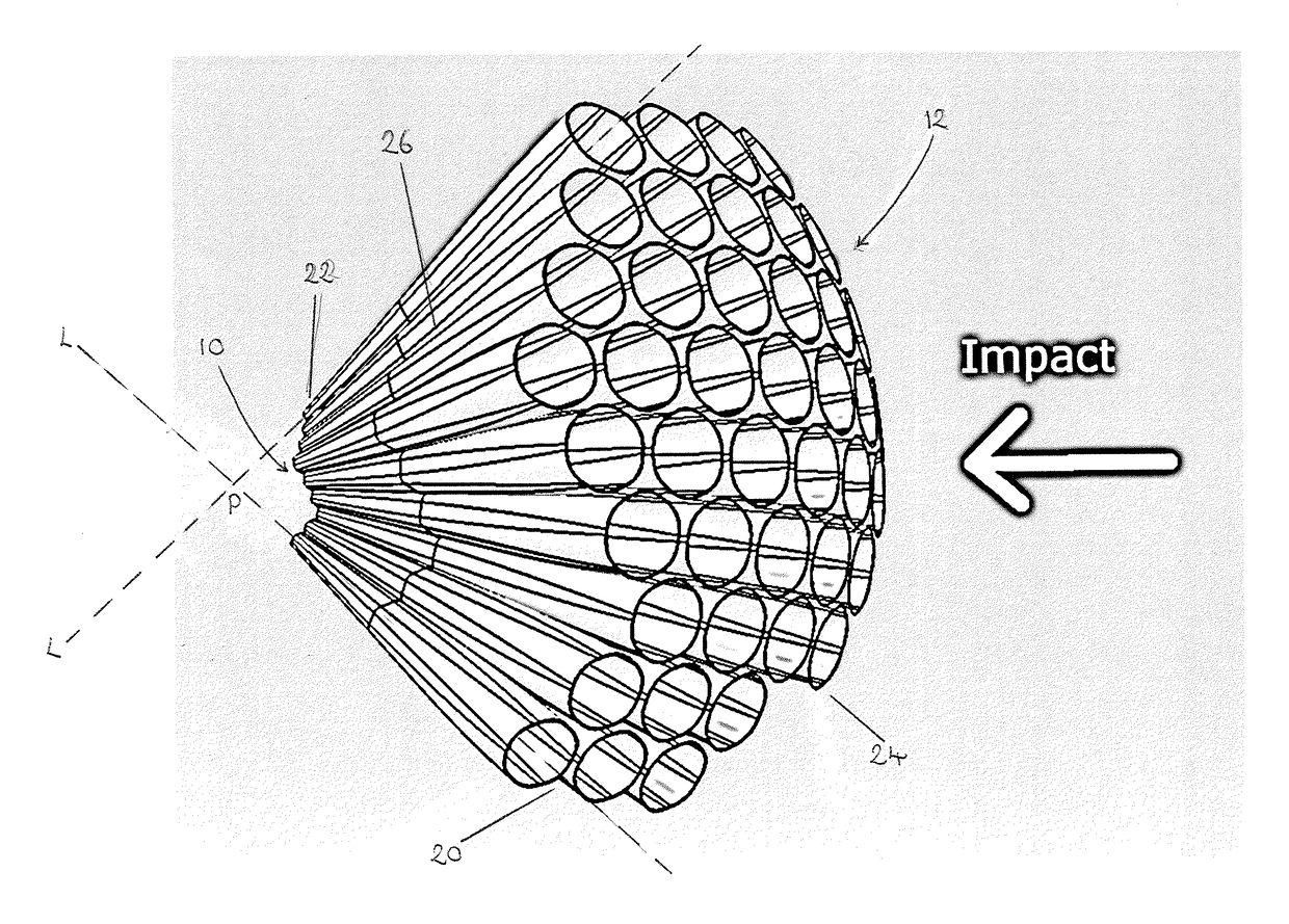
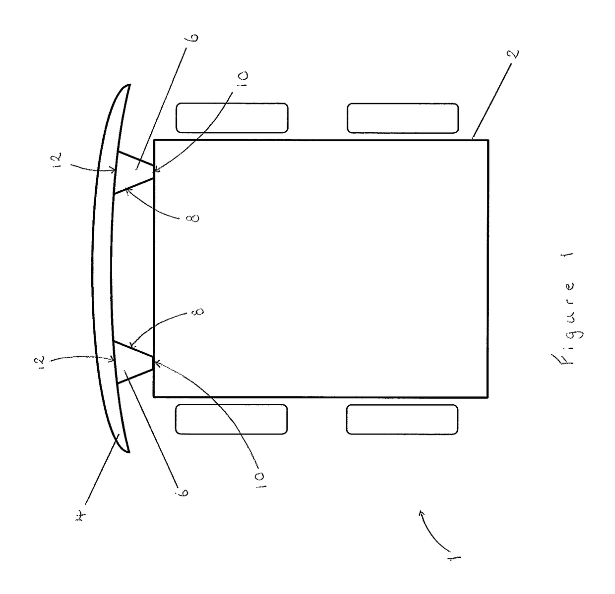
[0035]Referring to FIG. 1, a part of a vehicle 1 is shown in schematic form comprising a structural frame 2, such as a monocoque or chassis, at the front of which is mounted a bumper 4, or fender. The bumper 4 is mounted to the structural frame 2 by way of two impact energy absorbing devices 6 located towards the right and left hand sides (in the orientation shown in the figures) of the bumper 4. The impact energy absorbing devices 6 will hereinafter be referred to simply as ‘crash boxes’6.

[0036]The arrangement of mounting a bumper 4 to a structural frame 2 using one or more crash boxes 6 is generally known in the art. As the skilled person will understand, in the event of a largely frontal impact on the bumper 4, the crash boxes 6 act to absorb a portion of the energy of the impact by deforming plastically; that is to say, by crushing. Less impact energy is therefore transferred into the structural frame 2 which means that there is less risk of damage to the various components of t...


PUM


Abstract

An impact energy absorbing device for a vehicle includes a plurality of cells that are grouped together to form a matrix structure defining a mounting region and a contact region. The cells crush along their respective longitudinal axes when exposed to an impact force on the contact region. Each of the longitudinal axes of the plurality of cells in the matrix structure diverges with respect to neighboring cells in a direction from the mounting region to the contact region.

Description

RELATED APPLICATIONS[0001]This application is a 35 U.S.C. § 371 national stage application of PCT Application No. PCT / EP2016 / 051815, filed on Jan. 28, 2016, which claims priority from Great Britain Patent Application No. 1501399.8 filed on Jan. 28, 2015, the contents of which are incorporated herein by reference in their entireties. The above-referenced PCT International Application was published in the English language as international Publication No. WO 2016 / 120390 A1 on Aug. 4, 2016.TECHNICAL FIELD[0002]The present disclosure relates to an impact energy absorbing device for a vehicle and particularly, but not exclusively, to a sacrificial crash protection device for absorbing energy from impacts across a range of angles. Aspects of the invention relate to a device, to a vehicle structure component and to a vehicle.BACKGROUND[0003]Passenger vehicles are often provided with at least one sacrificial crash protection device mounted between the bumper and the structural frame of the v...

Claims


Application Information

Patent Timeline
Patent Type & Authority Patents(United States)
IPC IPC(8): B60R19/34B60R19/26
CPCB60R19/34B60R2019/264
Inventor LAKIC, ALEX
Owner JAGUAR LAND ROVER LTD
Why Eureka
Try Eureka