Apparatus for pest control
a technology for pests and accessories, applied in the field of accessories for pest control, to achieve the effect of effectively safely controlling pests, and reducing the reproductive potential of the target pest population
- Summary
- Abstract
- Description
- Claims
- Application Information
AI Technical Summary
Benefits of technology
Problems solved by technology
Method used
Image
Examples
example 1
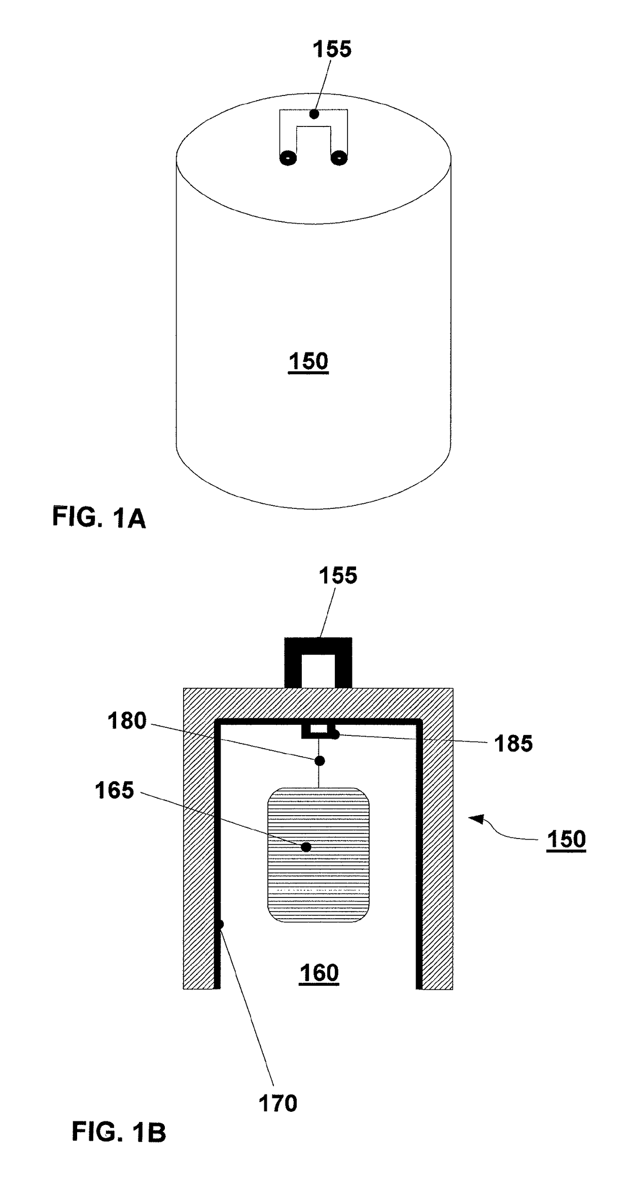
[0054]In FIGS. 1 and 5, an exemplary embodiment of the invention is shown which uses a dome.
[0055]In this embodiment, the apparatus consists of a dome 150, expediently made from hard plastic such as high-density polyethylene or PVC and manufactured using any commonly employed process.
[0056]The dimensions of the apparatus are selected so to provide mechanical stability and easy handling. The dome is circular in cross-section, with an internal diameter of approximately 6 cm and a height (from the opening 160 to the top of the apex) of approximately 8 cm to 10 cm.
[0057]The dome 150 is provided with an external bail or handle 155, whereby it may be suspended or otherwise fixed at the location of use, e. g. by tying it, using a line (not shown), to a branch of a fruit tree. The external bail or handle 155 is depicted as being a separate entity; it may, however, be produced as an integral part of the dome 150, or alternatively it may be manufactured from wire, as seen in FIG. 5. When the ...
example 2
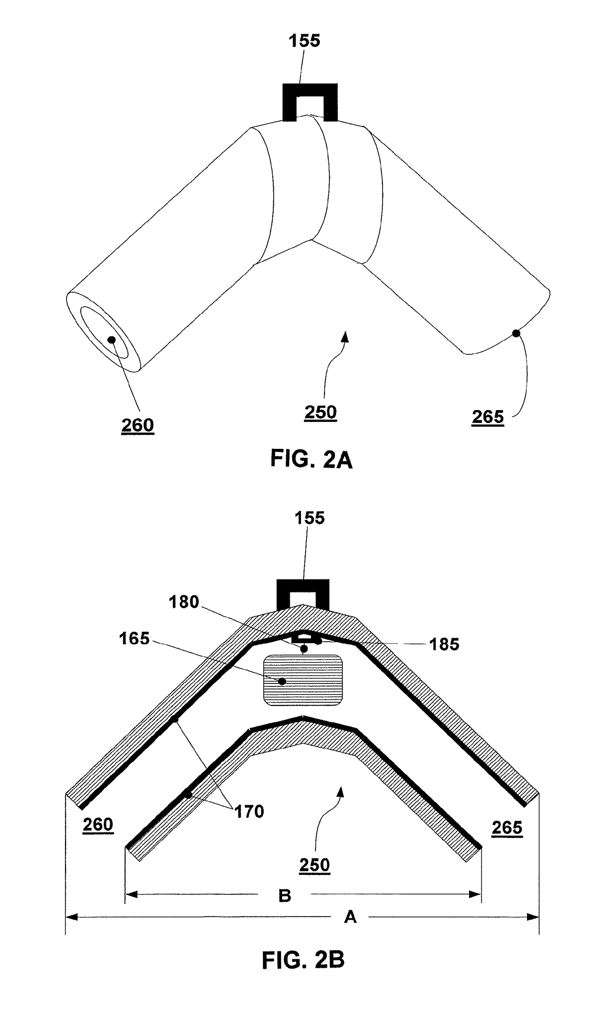
[0066]FIGS. 2A and 2B and FIG. 6, an exemplary embodiment of the invention is shown which differs from that of Example 1 in that it uses an angular tube 250, comprising two openings 260 and 265, in lieu of the dome. Otherwise, the structure of the apparatus essentially corresponds to that of Example 1. The embodiments of FIGS. 2A and 2B and FIG. 6 are therefore a “flow through” design as the pests may enter at one opening 260, flow through the device and exit at the other opening 265. The angle between the two arms of the tube 250 may e. g. 45° or 90°. As it can be seen from FIG. 6 the length A (see FIG. 2B) of the upper long edge in approximately 18 cm, the length B (see FIG. 2B) of the lower short edge in approximately 7 cm
[0067]FIGS. 4A and 4B illustrate the geometry of the embodiment shown in FIGS. 2A and 2B wherein FIG. 4A shows a cross-section through an apparatus being bent more whereas FIG. 4B correspondingly depicts the geometry of a preferred apparatus of the invention bei...
PUM
 Abstract
Description
Claims
Application Information
 - R&D
- Intellectual Property
- Life Sciences
- Materials
- Tech Scout
- Unparalleled Data Quality
- Higher Quality Content
- 60% Fewer Hallucinations
Browse by: Latest US Patents, China's latest patents, Technical Efficacy Thesaurus, Application Domain, Technology Topic, Popular Technical Reports.
© 2025 PatSnap. All rights reserved.Legal|Privacy policy|Modern Slavery Act Transparency Statement|Sitemap|About US| Contact US: help@patsnap.com


