
Apparatus for Pest Control

a technology for pests and accessories, applied in the field of accessories for pest control, to achieve the effect of effectively safely controlling pests, and reducing the reproductive potential of the target pest population

Inactive Publication Date: 2014-12-18
BASF AG
View PDF24 Cites 3 Cited by
  • Summary
  • Abstract
  • Description
  • Claims
  • Application Information

AI Technical Summary

Benefits of technology

The present invention provides an apparatus for safely controlling pests, particularly those in the horticultural industry. This apparatus reduces the likelihood of accumulating dead pests and effectively reduces the reproductive potential of the target pest population. The apparatus uses a pesticide in a hollow station that allows the target pests to escape and contaminate other members of their own species during their normal social interactions. This "cascade effect of mortality" is particularly useful for reducing the population's overall reproductive potential, especially with tephritids which perform sophisticated mating ceremonies and allow for contact between tainted and untainted individuals of both sexes.

Problems solved by technology

Tephritids are particularly susceptible to this effect as they usually perform sophisticated mating ceremonies, allowing for plenty of contact between tainted and untainted individuals of both sexes.

Method used


Image

  • Apparatus for Pest Control
  • Apparatus for Pest Control
  • Apparatus for Pest Control

Examples


example 1

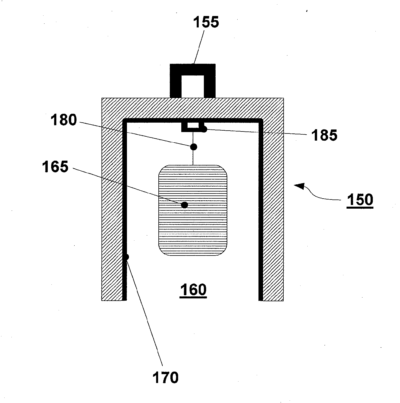
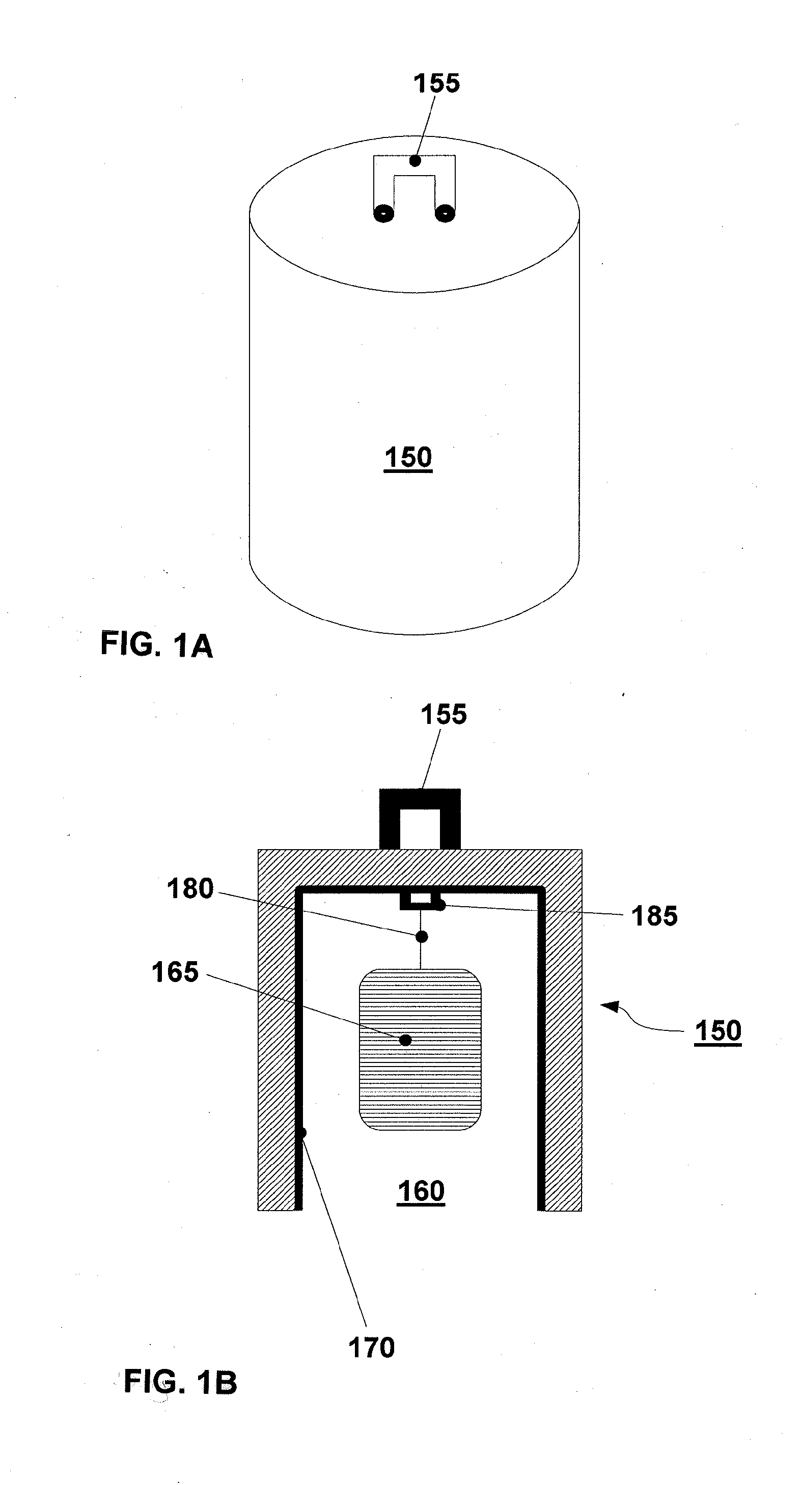
[0054]In FIGS. 1 and 5, an exemplary embodiment of the invention is shown which uses a dome.

[0055]In this embodiment, the apparatus consists of a dome 150, expediently made from hard plastic such as high-density polyethylene or PVC and manufactured using any commonly employed process.

[0056]The dimensions of the apparatus are selected so to provide mechanical stability and easy handling. The dome is circular in cross-section, with an internal diameter of approximately 6 cm and a height (from the opening 160 to the top of the apex) of approximately 8 cm to 10 cm.

[0057]The dome 150 is provided with an external bail or handle 155, whereby it may be suspended or otherwise fixed at the location of use, e. g. by tying it, using a line (not shown), to a branch of a fruit tree. The external bail or handle 155 is depicted as being a separate entity; it may, however, be produced as an integral part of the dome 150, or alternatively it may be manufactured from wire, as seen in FIG. 5. When the ...

example 2

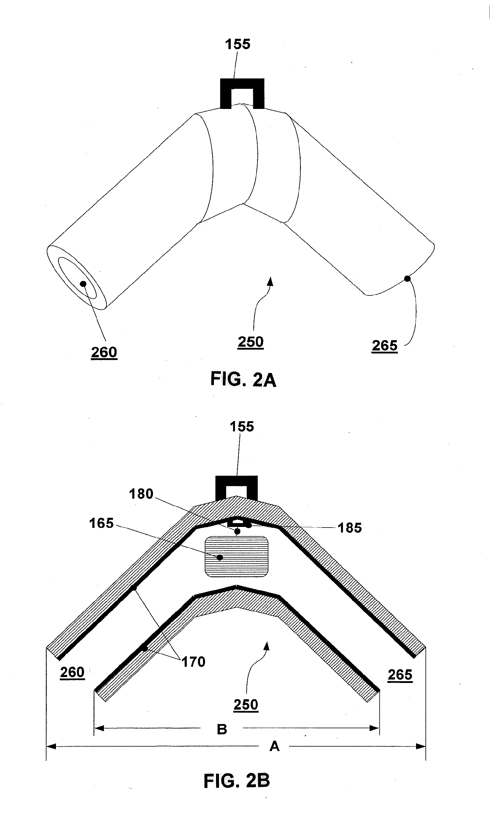
[0066]FIGS. 2A and 2B and FIG. 6, an exemplary embodiment of the invention is shown which differs from that of Example 1 in that it uses an angular tube 250, comprising two openings 260 and 265, in lieu of the dome. Otherwise, the structure of the apparatus essentially corresponds to that of Example 1. The embodiments of FIGS. 2A and 2B and FIG. 6 are therefore a “flow through” design as the pests may enter at one opening 260, flow through the device and exit at the other opening 265. The angle between the two arms of the tube 250 may e. g. 45° or 90°. As it can be seen from FIG. 6 the length A (see FIG. 2B) of the upper long edge in approximately 18 cm, the length B (see FIG. 2B) of the lower short edge in approximately 7 cm

[0067]FIGS. 4A and 4B illustrate the geometry of the embodiment shown in FIGS. 2A and 2B wherein FIG. 4A shows a cross-section through an apparatus being bent more whereas FIG. 4B correspondingly depicts the geometry of a preferred apparatus of the invention bei...


PUM


Abstract

The present invention relates to an apparatus for pest control; and to the use of said apparatus for pest control. The apparatus comprises a hollow station forming at least one entrance for the pests to be controlled; a pheromone of a pest to be controlled; and a contact pesticide for the pests to be controlled, said contact pesticide being provided inside said hollow station, and the hollow station being designed to prevent the pests from remaining within said hollow station without expenditure of energy.

Description

CROSS-REFERENCES TO RELATED APPLICATIONS[0001]This application is a continuation application of U.S. application Ser. No. 12 / 863,886, filed Jul. 21, 2010, which is a National Stage application of International Application No. PCT / EP2009 / 050765 filed Jan. 23, 2009, the entire contents of which is hereby incorporated by reference. This application also claims the benefit of U.S. Provisional Application No. 61 / 023,553 filed Jan. 25, 2008, the entire contents of which is hereby incorporated herein by reference.BACKGROUND OF THE INVENTION[0002]The present invention relates to an apparatus for pest control; and to the use of said apparatus for pest control.[0003]A number of the more than 3000 species of tephritid fruit flies, in particular those of the genera Ceratitis, Dacus, Bactrocera and Rhagoletis, are important horticultural pests. The insects lay their eggs into mostly species-specific host plants after which many of the species are named (e. g. olives for Bactrocera oleae, squashe...

Claims


Application Information

Patent Timeline
Patent Type & Authority Applications(United States)
IPC IPC(8): A01M1/20A01M1/02
CPCA01M1/02A01M1/2016
Inventor BOLIN, DAVID G.
Owner BASF AG
Learn More