Check patentability & draft patents in minutes with Patsnap Eureka AI!

Power conversion system

a power supply and power conversion technology, applied in the direction of electric devices, stopping arrangements, transportation and packaging, etc., can solve the problem of power supply loss of driving an inverter control circui

Active Publication Date: 2019-01-08
MITSUBISHI ELECTRIC CORP
View PDF5 Cites 0 Cited by
  • Summary
  • Abstract
  • Description
  • Claims
  • Application Information

AI Technical Summary

Benefits of technology

The system effectively releases high voltage charges from the secondary smoothing capacitor after motor rotation speed reduction, maintaining the power supply for the inverter control unit and ensuring safety by controlling the inter-terminal voltage, thus preventing electrocution and enabling swift discharge operations.

Problems solved by technology

However, the method proposed in Patent Documents 1 and 2 and Patent Document 3 is such that there is concern about losing a power supply for driving an inverter control circuit when reducing the motor rotation speed.

Method used


Image

  • Power conversion system
  • Power conversion system
  • Power conversion system

Examples


first embodiment

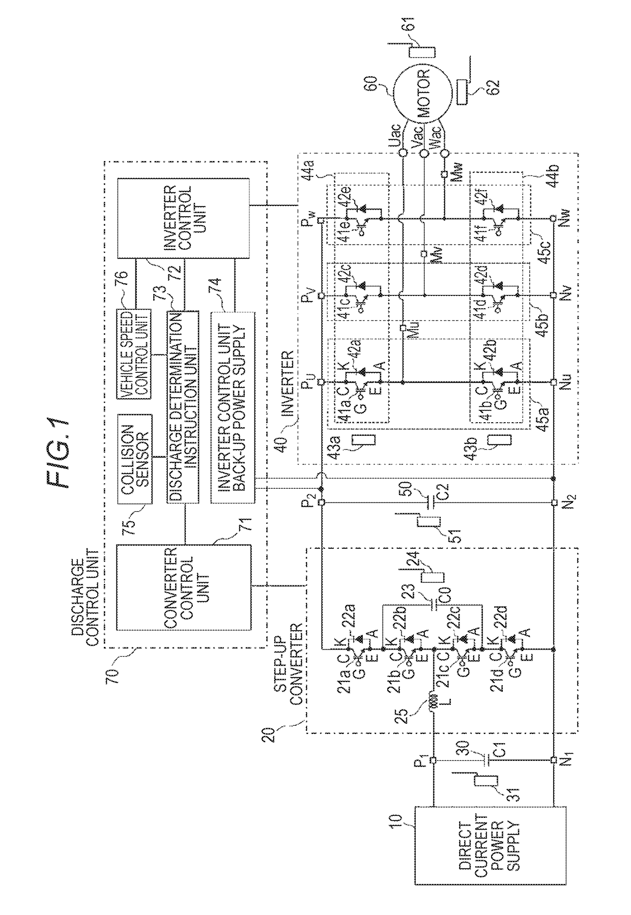
[0019]FIG. 1 is a configuration diagram showing a power conversion system according to a first embodiment of the invention.

[0020]As shown in FIG. 1, the power conversion system according to the first embodiment of the invention includes a direct current power supply 10, a step-up converter 20, a primary smoothing capacitor 30, a primary voltage sensor 31, which is means of detecting inter-terminal voltage of the primary smoothing capacitor 30, an inverter 40, a secondary smoothing capacitor 50, a secondary voltage sensor 51, which is means of detecting inter-terminal voltage of the secondary smoothing capacitor 50, a 3-phase alternating current motor 60, a motor rotation speed sensor 61, which is means of detecting a rotation speed of the 3-phase alternating current motor 60, a motor temperature sensor 62, and a discharge control unit 70.

[0021]The direct current power supply 10 is rechargeable, and carries out an exchange of power with the 3-phase alternating current motor 60 via th...


PUM


Abstract

When a motor rotation speed is equal to or greater than a predetermined rotation speed when an automobile collision is detected or when power stops, a motor rotation speed reduction control is carried out by an inverter control unit, and when an inter-terminal voltage of a secondary smoothing capacitor drops below a predetermined voltage during the motor rotation speed reduction control, the motor rotation speed reduction control is stopped, whereby induction voltage caused by motor rotation is applied to the secondary smoothing capacitor, the inter-terminal voltage of the secondary smoothing capacitor is raised, and the motor rotation speed reduction control is carried out while keeping the inter-terminal voltage of the secondary smoothing capacitor within an operating voltage range of the inverter control unit.

Description

BACKGROUND OF THE INVENTIONField of the Invention[0001]The present invention relates to a power conversion system mounted in a vehicle such as a hybrid automobile, and in particular, relates to a power conversion system that carries out motor rotation speed reduction control in accordance with vehicle information when a vehicle collision is detected or when power stops.Description of the Related Art[0002]There is an existing hybrid automobile that includes a rechargeable direct current power supply, a step-up converter that steps up a direct current voltage supplied from the direct current power supply, a primary smoothing capacitor that smooths voltage between the direct current power supply and step-up converter, an inverter that converts high direct current voltage output from the step-up converter into alternating current voltage, a secondary smoothing capacitor that smooths voltage between the step-up converter and inverter, and a 3-phase alternating current motor by which driv...

Claims


Application Information

Patent Timeline
Patent Type & Authority Patents(United States)
IPC IPC(8): H02P27/04B60L3/00B60L3/04H02P6/24
CPCB60L3/04B60L3/0007H02P6/24B60L2240/425B60L2240/421H02M7/53871H02P27/06B60L3/003B60L15/007B60L2210/10B60L2210/40B60L2240/525B60L2240/527Y02T10/64Y02T10/72
Inventor TAKEGAWA, KAZUKINAKAJIMA, KOJIISHIBASHI, SATOSHIOTSUKA, KAZUHIKO
Owner MITSUBISHI ELECTRIC CORP
Features
  • R&D
  • Intellectual Property
  • Life Sciences
  • Materials
  • Tech Scout
  • Unparalleled Data Quality
  • Higher Quality Content
  • 60% Fewer Hallucinations
Learn More