Welding electrode holder

a technology for welding electrodes and holders, which is applied in the direction of shielding electrode holders, welding electrode features, and electrode supporting devices, etc., can solve the problems of not firmly and securely holding the electrode, the process of electrode replacement is very slow and cumbersome, and the welder is too busy, etc., to achieve the effect of slipping comfortably and safely by the user

Active Publication Date: 2019-04-16
TOWNSEND CARL
View PDF14 Cites 0 Cited by
  • Summary
  • Abstract
  • Description
  • Claims
  • Application Information

AI Technical Summary

Benefits of technology

[0009]In one aspect, a welding electrode holder is provided. The electrode holder is formed by a body which provides the structure for the electrode holder. The body has a handle and a jaws region, with the body defining an interior aperture. A pair of jaws are positioned within the jaws region of the body. The jaws are movable between an open position and a closed position, and are biased towards the closed position. An opening on a front face of the jaws region of the body allows an electrode to pass through the body to access the pair of jaws. A tab extends out of the body at the handle. This tab is in communication with at least one of the pair of jaws, and is movable to bring the pair of jaws between the open and closed position. A cable connector is positioned at the bottom of the handle. The cable connector is configured to connect a cable from a welding machine to the electrode holder. An electrical connector is positioned within the aperture of the body and provides electrical communication between the cable connector, through the body to at least one of the pair of jaws. The jaws are oriented nearly perpendicular to the handle, and extend outward from the handle nearly perpendicularly to the handle. As such the handle can be gripped comfortably and safely by the user while the electrode extends away from the user, towards the welding surface.
[0011]In this aspect, a thumb tab extends from a portion of the handle, with the handle defining an aperture that allows the protruding thumb tab to slide along a part of a length of the handle. The thumb tab is in communication with the bottom jaw and is movable to bring the bottom jaw between the open and closed position. A cable connector is positioned at the bottom of the handle. The cable connector is configured to connect a cable from a welding machine to the electrode holder. Within the handle, a metal shaft extends from the cable connector at its proximal end, through the body to a top of the body and connecting at its distal end to the top jaw. The metal shaft provides electrical communication between the cable connector, through the body interior aperture to the pair of jaws. Further, the bottom jaw forms an aperture through which the metal shaft passes, with the bottom jaw being slidable along the shaft when moving between the open and closed positions. The jaws are oriented nearly perpendicular to the handle, and extend nearly perpendicularly to the handle. As such the handle can be gripped comfortably and safely by the user while the electrode extends away from the user, towards the welding surface.

Problems solved by technology

The spin loose and spin tight electrode holders suffer from making the process of replacing electrodes very slow and cumbersome.
Replacement of electrodes must be done frequently throughout a day's work, which results in excessive down time for a welder when using such an electrode holder.
The parallel jaw clamp electrode holders, while allowing easy replacement of electrodes, do not firmly and securely hold the electrode.
This makes it more difficult to use, especially when finesse is required, and can lead to unsafe and unstable operation.

Method used


Image

  • Welding electrode holder
  • Welding electrode holder
  • Welding electrode holder

Examples


Embodiment Construction

[0018]The detailed description set forth below in connection with the appended drawings is intended as a description of presently preferred embodiments of the invention and does not represent the only forms in which the present invention may be constructed and / or utilized. The description sets forth the functions and the sequence of steps for constructing and operating the invention in connection with the illustrated embodiments.

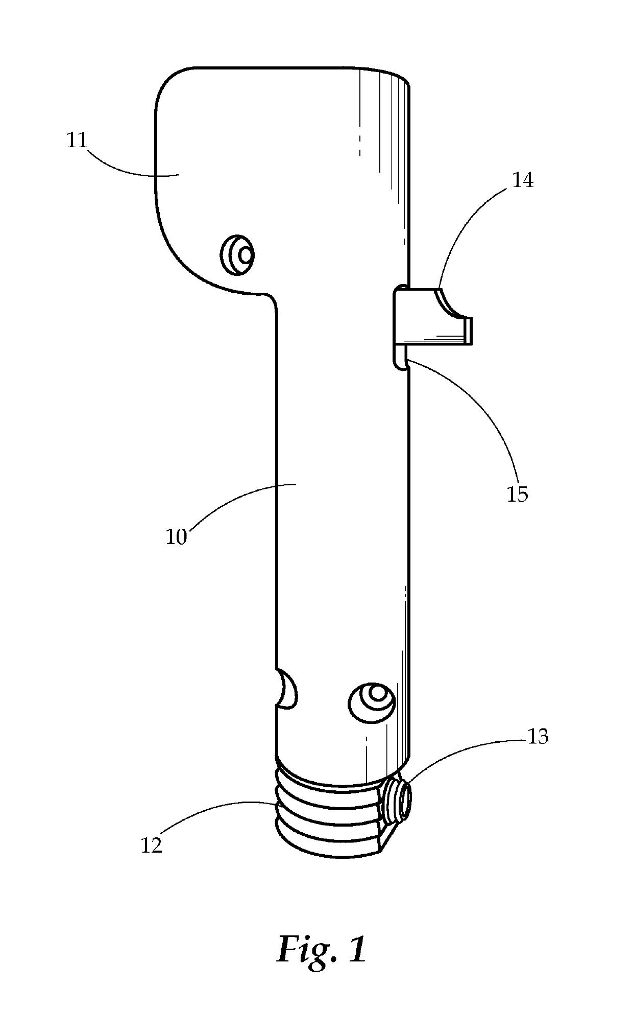
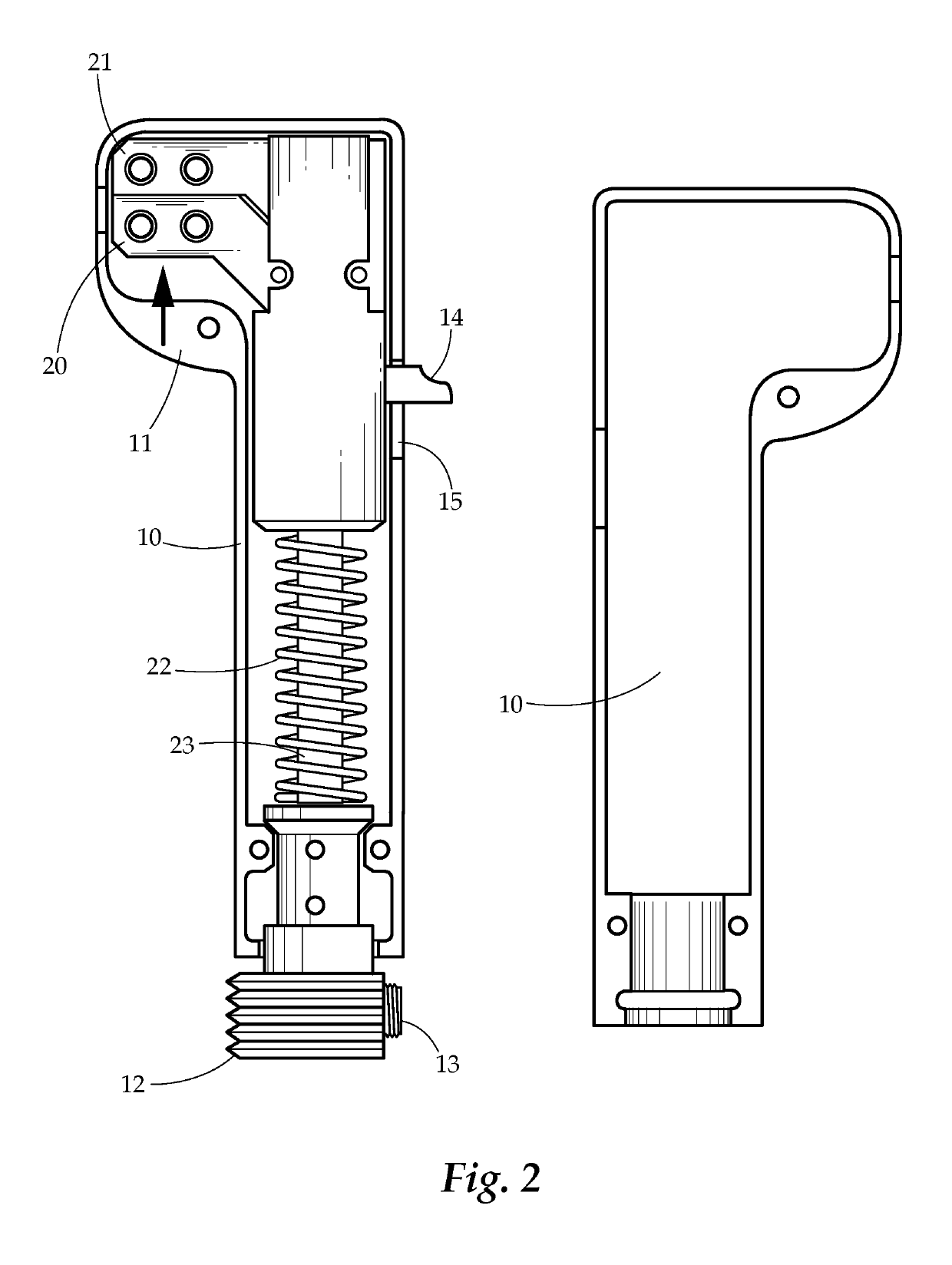
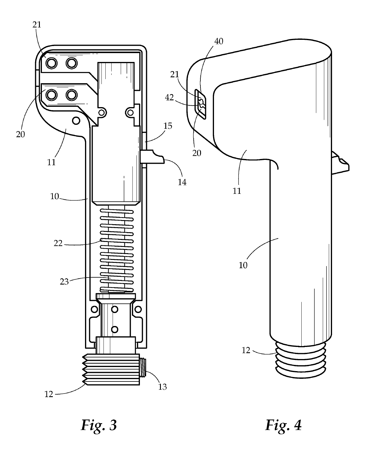
[0019]Generally, the present invention concerns an electrode holder having spring loaded jaws that are oriented perpendicularly to a handle of the holder. The electrode holder comprises a body having a handle and a jaw region. In the jaw region are two jaws that are movable between an open and closed position. A spring or other force-applying structure provides a bias to urge the jaws towards the closed position, such that a welding electrode may be securely held in place between the jaws. A thumb tab or other structure extends out of the handle to allow a u...


PUM

PropertyMeasurementUnit
forceaaaaaaaaaa
lengthaaaaaaaaaa
electrically conductiveaaaaaaaaaa

Abstract

A welding electrode holder is provided. The welding electrode holder comprises a handle and electrode clamps extending nearly perpendicularly from the handle, thereby providing easy loading and unloading of electrodes, coupled with secure holding of the electrode during operation.

Description

BACKGROUND OF THE INVENTION[0001]Field of the Invention[0002]The present invention relates generally to welding electrode holders. More particularly the present invention relates to a device that has spring loaded jaws to hold a welding electrode perpendicularly to the electrode holder handle.[0003]Description of Related Art[0004]Traditional electrode holders for stick welding include either a spin loose and spin tight electrode holder, or a clamp having jaws that are parallel to the electrode holder handle. Each of these suffers from a number of disadvantages.[0005]The spin loose and spin tight electrode holders suffer from making the process of replacing electrodes very slow and cumbersome. Replacement of electrodes must be done frequently throughout a day's work, which results in excessive down time for a welder when using such an electrode holder.[0006]The parallel jaw clamp electrode holders, while allowing easy replacement of electrodes, do not firmly and securely hold the ele...

Claims


Application Information

Patent Timeline
Patent Type & Authority Patents(United States)
IPC IPC(8): B23K9/28
CPCB23K9/282
Inventor TOWNSEND, CARL
Owner TOWNSEND CARL
Why Eureka
Try Eureka