Welding Electrode Holder

Active Publication Date: 2017-03-30
TOWNSEND CARL
View PDF4 Cites 8 Cited by
  • Summary
  • Abstract
  • Description
  • Claims
  • Application Information

AI Technical Summary

Benefits of technology

[0013]The metal shaft provides electrical communication between the cable connector, through the body interior aperture to the pair of jaws. Further, the bottom jaw forms an aperture through which the metal shaft passes, with the bottom jaw being slidable along the shaft when moving bet

Problems solved by technology

The spin loose and spin tight electrode holders suffer from making the process of replacing electrodes very slow and cumbersome.
Replacement of electrodes must be done frequently throughout a day's work, which results in excessive down time for a welder when using such an

Method used


Image

  • Welding Electrode Holder
  • Welding Electrode Holder
  • Welding Electrode Holder

Examples


Embodiment Construction

[0020]The detailed description set forth below in connection with the appended drawings is intended as a description of presently preferred embodiments of the invention and does not represent the only forms in which the present invention may be constructed and / or utilized. The description sets forth the functions and the sequence of steps for constructing and operating the invention in connection with the illustrated embodiments.

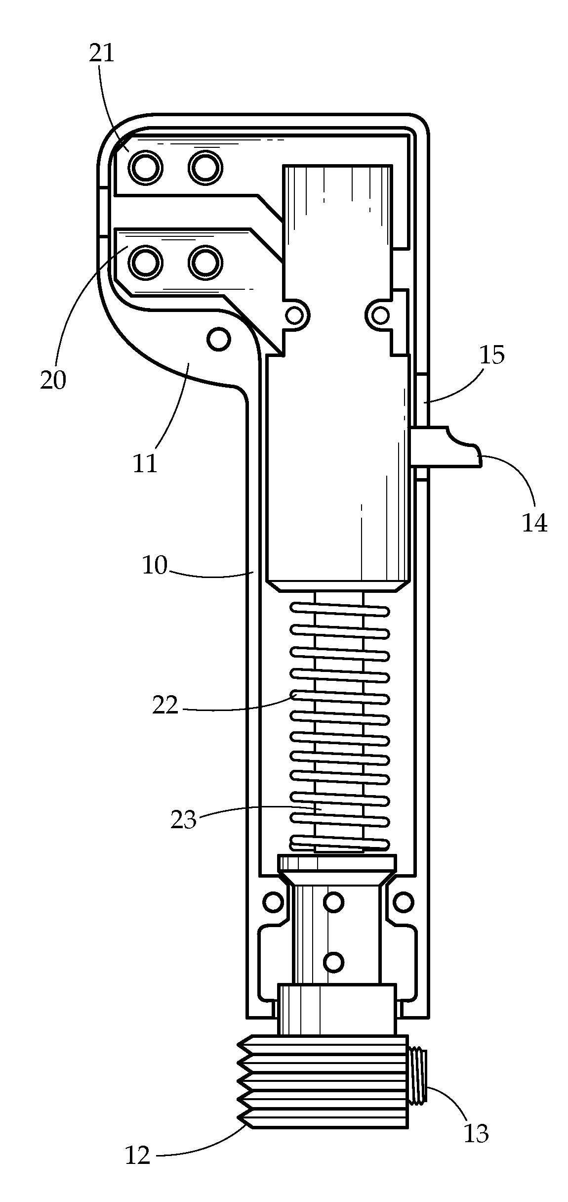
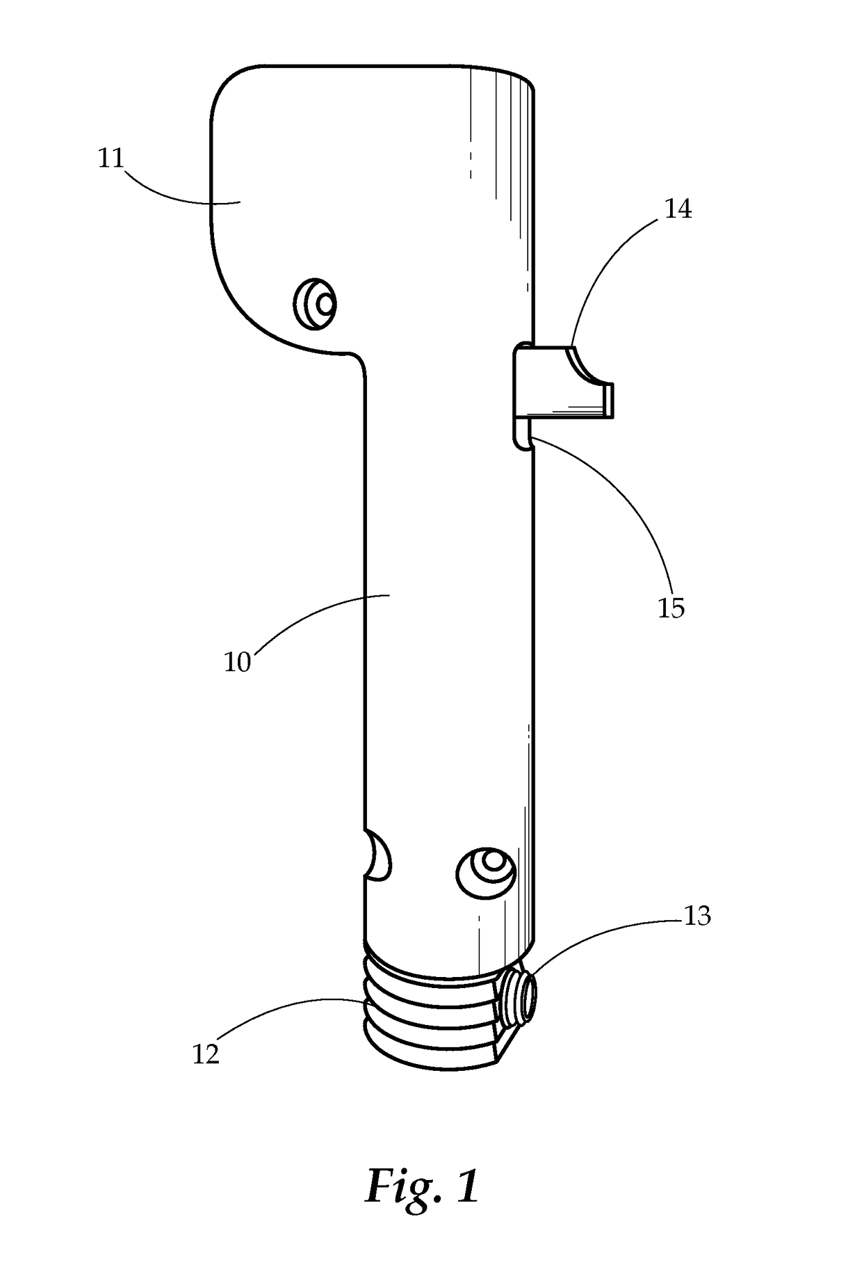
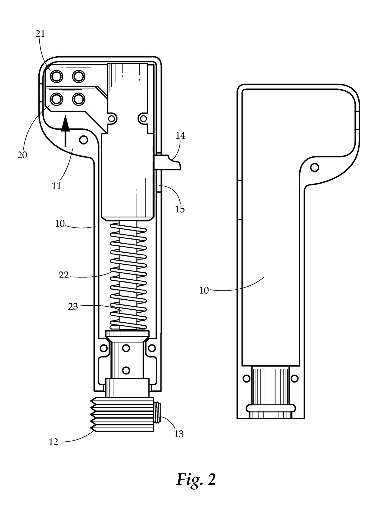
[0021]Generally, the present invention concerns an electrode holder having spring loaded jaws that are oriented perpendicularly to a handle of the holder. The electrode holder comprises a body having a handle and a jaw region. In the jaw region are two jaws that are movable between an open and closed position. A spring or other force-applying structure provides a bias to urge the jaws towards the closed position, such that a welding electrode may be securely held in place between the jaws. A thumb tab or other structure extends out of the handle to allow a u...


PUM

PropertyMeasurementUnit
Forceaaaaaaaaaa
Electrical conductivityaaaaaaaaaa
Lengthaaaaaaaaaa

Abstract

A welding electrode holder is provided. The welding electrode holder comprises a handle and electrode clamps extending nearly perpendicularly from the handle, thereby providing easy loading and unloading of electrodes, coupled with secure holding of the electrode during operation.

Description

BACKGROUND OF THE INVENTION[0001]Field of the Invention[0002]The present invention relates generally to welding electrode holders. More particularly the present invention relates to a device that has spring loaded jaws to hold a welding electrode perpendicularly to the electrode holder handle.[0003]Description of Related Art[0004]Traditional electrode holders for stick welding include either a spin loose and spin tight electrode holder, or a clamp having jaws that are parallel to the electrode holder handle. Each of these suffers from a number of disadvantages.[0005]The spin loose and spin tight electrode holders suffer from making the process of replacing electrodes very slow and cumbersome. Replacement of electrodes must be done frequently throughout a day's work, which results in excessive down time for a welder when using such an electrode holder.[0006]The parallel jaw clamp electrode holders, while allowing easy replacement of electrodes, do not firmly and securely hold the ele...

Claims


Application Information

Patent Timeline
IPC IPC(8): B23K9/28B23K9/12H05B7/109
CPCB23K9/282B23K9/122H05B7/109
Inventor TOWNSEND, CARL
Owner TOWNSEND CARL
Why Eureka
Try Eureka