

Exhaust heat recovery device
a heat recovery device and exhaust heat technology, applied in the direction of engines, mechanical equipment, machines/engines, etc., can solve the problems of abnormal sound caused by cooling water boiling at the heat recovery unit, low heat transfer ability of regions that are not fastened at the portion connecting the first pipe with the second pipe, and the effect of efficient long-term
- Summary
- Abstract
- Description
- Claims
- Application Information
AI Technical Summary
Benefits of technology
Problems solved by technology
Method used
Image

Examples
first embodiment
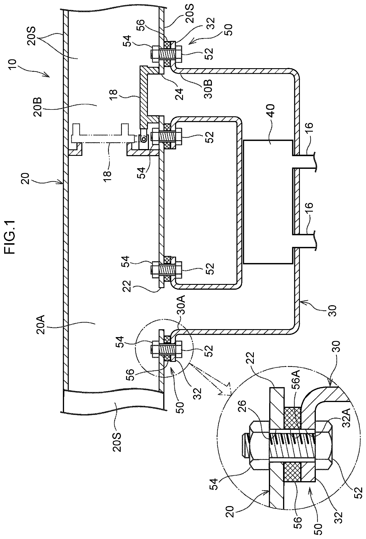
[0035]An exhaust heat recovery device 10 relating to a first embodiment is described hereinafter by using FIG. 1 and FIG. 2. Then, a heat transfer suppressing mechanism 50 that is applied to the exhaust heat recovery device 10 is described. Note that, hereinafter, there are cases in which the upstream side and the downstream side in the direction of flowing of exhaust gas are simply called the “upstream side” and the “downstream side.
[0036](Regarding the Exhaust Heat Recovery Device 10)
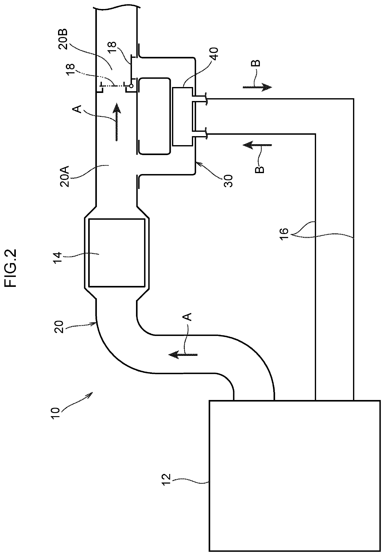
[0037]As shown in FIG. 2, the exhaust heat recovery device 10 is a device that recovers, by heat exchange with cooling water that is within a heat recovery unit 40 that is described later, heat of exhaust gas of an engine 12 of an automobile, and uses the heat in promoting warming-up of the engine 12 and the like.
[0038]As shown in FIG. 1, the exhaust heat recovery device 10 has a first pipe 20 that is pipe-shaped. In the present embodiment, the first pipe 20 is formed in the shape of a pipe by joining...
second embodiment
[0060]An exhaust heat recovery device 60 of a second embodiment is described hereinafter by using FIG. 4. The exhaust heat recovery device 60 of the second embodiment is structured similarly to the exhaust heat recovery device 10 of the first embodiment, except for the heat transfer suppressing mechanisms 50. The heat transfer suppressing mechanisms 50 of the exhaust heat recovery device 60 are described hereinafter. Note that, in FIG. 4, parts that are structured similarly to the exhaust heat recovery device 10 of the first embodiment are denoted by the same reference numerals.
[0061]The heat insulating material 56, the bolt 52 and the weld nut 54 are omitted from the heat transfer suppressing mechanism 50 of the exhaust heat recovery device 60, and the second pipe flange 32 of the second pipe 30 is directly joined to the first pipe 20 by laser welding. Note that, in FIG. 4, in order to make it easy to understand welded width W1 of a welded portion 58 of the second pipe flange 32 an...
third embodiment
[0064]An exhaust heat recovery device 70 of a third embodiment is described hereinafter by using FIG. 5. The exhaust heat recovery device 70 of the third embodiment is structured similarly to the exhaust heat recovery device 10 of the first embodiment, except for the heat transfer suppressing mechanisms 50. The heat transfer suppressing mechanisms 50 of the exhaust heat recovery device 70 are described hereinafter. Note that, in FIG. 5, parts that are structured similarly to the exhaust heat recovery device 10 of the first embodiment are denoted by the same reference numerals.
[0065]The heat insulating material 56 is omitted from the heat transfer suppressing mechanism 50 of the exhaust heat recovery device 70. Further, the heat transfer suppressing mechanisms 50 of the exhaust heat recovery device 70 have first pipe flanges 28 that serve as “first flanges” and that are formed at the first pipe 20. The first pipe flanges 28 are formed respectively at the peripheral edge portions of t...
PUM
 Abstract
Description
Claims
Application Information