Exhaust heat recovery unit

a heat recovery unit and exhaust heat technology, applied in indirect heat exchangers, machines/engines, lighting and heating apparatus, etc., can solve the problem of boiling of coolant (heat medium) that has stopped flowing

Active Publication Date: 2020-04-21
TOYOTA JIDOSHA KK +1
View PDF7 Cites 0 Cited by
  • Summary
  • Abstract
  • Description
  • Claims
  • Application Information

AI Technical Summary

Benefits of technology

[0069]The present disclosure can suppress boiling of the heat medium caused by heat from the exhaust pipe being transmitted to the heat exchanger.

Problems solved by technology

Additionally, in a case where the engine has been stopped after high-load travel, there is the concern that, when the heat of the exhaust pipe that has reached a high temperature because of the exhaust gas at the time of the high-load travel is transmitted to the heat exchanger, the coolant (heat medium) that has stopped flowing will boil.

Method used


Image

  • Exhaust heat recovery unit
  • Exhaust heat recovery unit
  • Exhaust heat recovery unit

Examples


example modifications

[0053]In the present embodiment, a coolant is used as the heat medium, but the heat medium is not limited to this. As the heat medium, an automatic transmission fluid (ATF) or a continuously variable transmission (CTV) fluid may be used, and fluids such as liquids and gases used in heat exchange can be widely applied.

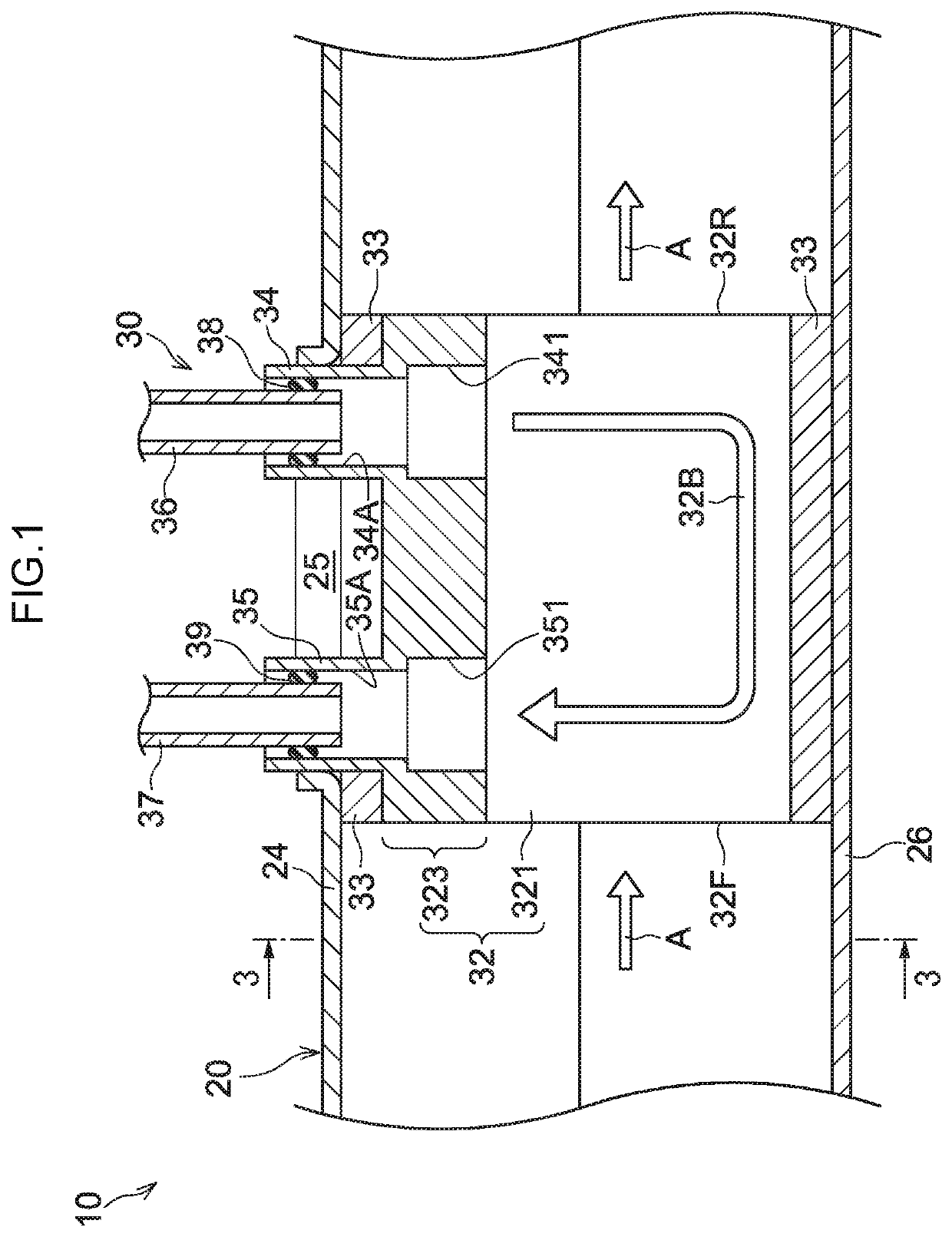
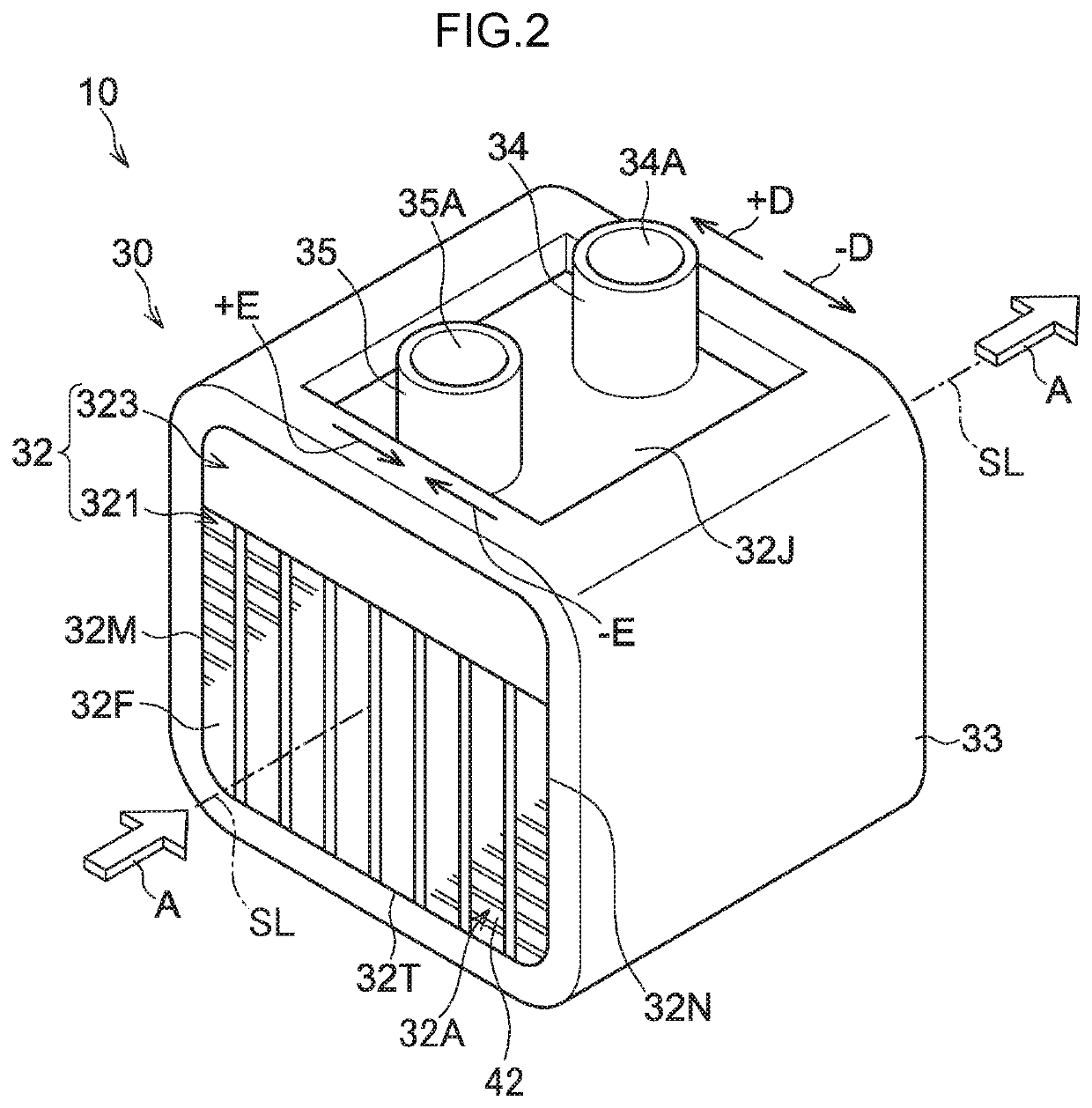
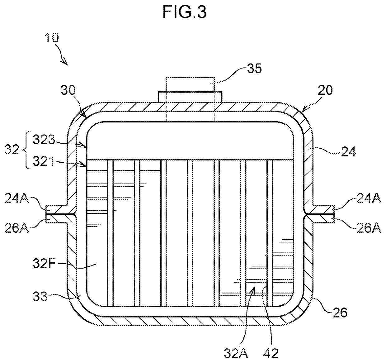
[0054]Furthermore, in the embodiment, the retention member 33 is disposed in a substantially rectangular shape so as to surround the virtual line SL, but the retention member 33 is not limited to this. For example, the retention member 33 may also have a configuration where it is disposed in a substantially circular shape about the virtual line SL. That is, the retention member 33 may be disposed in any shape so long as the configuration where the retention member 33 is disposed on the periphery of the heat exchanger 32 around the virtual line SL is a configuration where the retention member 33 is disposed so as to surround the virtual line SL.

[0055]The present disclosu...


PUM


Abstract

An exhaust heat recovery unit, includes: a heat exchanger that is provided inside an exhaust pipe through which exhaust gas flows, the heat exchange being formed from silicon carbide, and the heat exchanger performing heat exchange between the exhaust gas and a heat medium; and a retention member that is provided at the periphery of the heat exchanger, is formed of a ceramic sheet or an expandable graphite sheet, and is sandwiched between the exhaust pipe and the heat exchanger, thereby retaining the heat exchanger in the exhaust pipe.

Description

CROSS-REFERENCE TO RELATED APPLICATION[0001]This application is based on and claims priority under 35 USC 119 from Japanese Patent Application No. 2017-186509 filed on Sep. 27, 2017, which is incorporated by reference herein.BACKGROUNDTechnical Field[0002]The present disclosure relates to an exhaust heat recovery unit.Related Art[0003]Japanese Patent Application Laid-open (JP-A) No. 2016-223717 discloses a heat exchanger where a metal band that uses a metal such as stainless steel (SUS) is interposed between a ceramic honeycomb structure and a case. By installing the heat exchanger of JP-A No. 2016-223717 in an automobile, exhaust gas and a heat medium such as a coolant can be made to flow in cells of the honeycomb structure and exchange heat.[0004]Here, when the engine is stopped, normally the flow of the coolant (heat medium) inside the heat exchanger stops. Additionally, in a case where the engine has been stopped after high-load travel, there is the concern that, when the heat o...

Claims


Application Information

Patent Timeline
Patent Type & Authority Patents(United States)
IPC IPC(8): F01N13/18F01N5/02F02G5/02
CPCF01N13/1894F02G5/02F01N13/1838F01N5/02F01N2240/02F01N2470/10F28F21/00F28F21/02F28F21/04Y02T10/12F28F9/001F28D21/0003F28D1/0206
Inventor MURATA, TOSHIOKOGA, YOSHIHIRO
Owner TOYOTA JIDOSHA KK
Why Eureka
Try Eureka