Intercooler

a technology of intercooler and cooling water, which is applied in the direction of indirect heat exchangers, machines/engines, light and heating apparatus, etc., can solve the problems of reducing the boiling point reducing the efficiency of the cooling water, and reducing the cooling water pressure loss, so as to reduce the strength and breakage, prevent the boiling of the second cooling water, and reduce the effect of pressure loss

Active Publication Date: 2020-05-19
DENSO CORP
View PDF35 Cites 0 Cited by
  • Summary
  • Abstract
  • Description
  • Claims
  • Application Information

AI Technical Summary

Benefits of technology

[0008]In view of the above, it is an object of the present disclosure to suppress a boiling of cooling medium in an intercooler which is configured to cool a supercharged intake air with two kinds of cooling medium having different temperature.
[0010]According to this, in the most upstream part in the flow direction of the supercharged intake air, the heat of the supercharged intake air is prevented from transmitted to the second cooling water in the outlet side passage through the fins. As a result, it is possible to suppress boiling of the second cooling water in the outlet side passage where the second cooling water may easily boil. Accordingly, temperature increase of components around the second outlet side flow path can be suppressed, and reduction in strength and breakage can be avoided.

Problems solved by technology

Since the hot cooling water flow path has the U-turn structure, a narrow flow path, and inner fins, a pressure loss of the cooling water may be large, and the boiling point of the cooling water may decrease.
As a result, the cooling water may boil in the downstream flow path in the hot cooling water path.
If the cooling water boils in the hot cooling water flow path, it may cause a temperature increase of components around the hot cooling water flow path, and accordingly a strength of the components may decrease and the components may be damaged.

Method used


Image

  • Intercooler
  • Intercooler
  • Intercooler

Examples


first embodiment

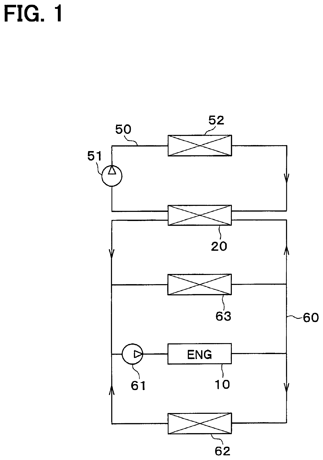
[0022]A first embodiment of the present disclosure will be described with reference to the drawings. In the first embodiment, an example in which an intercooler of the present disclosure is applied to a supercharged intake air cooling system for a vehicle will be described.

[0023]A supercharger (not shown) for supercharging intake air to an engine 10 is provided in an intake air system of the engine 10 of the vehicle (that is, an internal combustion engine). This supercharger is provided to compensate for the maximum output of the engine 10. That is, the vehicle of the present embodiment has the engine 10 made smaller for higher fuel efficiency and the supercharger is used to compensate for the maximum output reduced in exchange for making the engine 10 smaller.

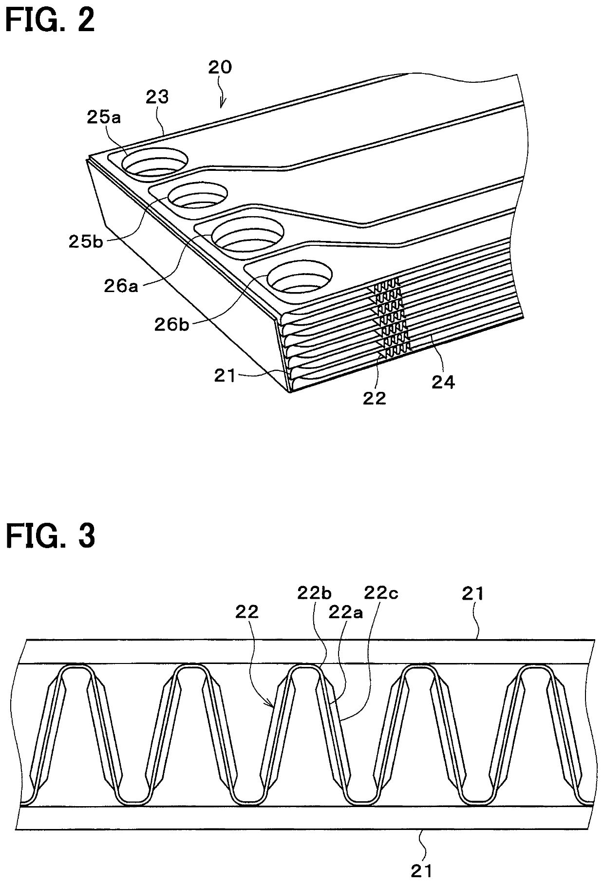
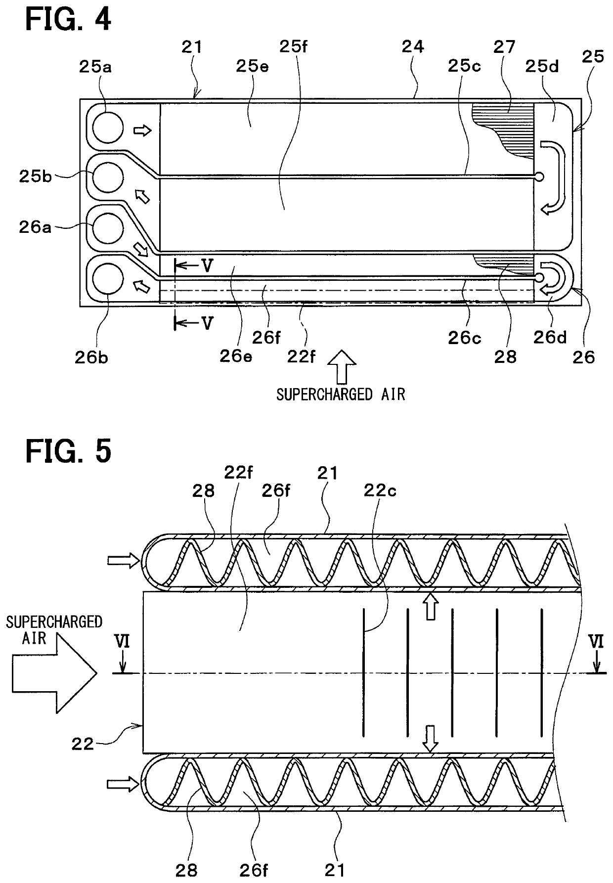
[0024]An intercooler 20 cooling engine intake air is located downstream of the supercharger in the intake air system with respect to a flow of the intake air. The intercooler 20 cools the supercharged intake air that has been ...

second embodiment

[0056]Next, a second embodiment of the present disclosure will be described. In the second embodiment, only parts different from the above-described first embodiment will be described.

[0057]FIG. 7 is a cross-sectional view of the fins 22, 29 of the second embodiment and corresponds to FIG. 6 of the first embodiment. As shown in FIG. 7, in the second embodiment, two types of fins 22, 29 are provided between adjacent flow path tubes21.

[0058]Louver fins 22 are provided on the downstream side in the flow direction of the supercharged intake air. The louver fins 22 of the second embodiment have the same configuration as the louver fins described in the first embodiment except that the upstream flat portion 22f is not provided. Offset fins 29 are provided on the upstream side in the flow direction of the supercharged intake air.

[0059]As shown in FIG. 8, the offset fin 29 has a corrugated shape in which wall portions 29a constituting flat portions and peak portions 29b constituting bent po...

third embodiment

[0065]Next, a third embodiment of the present disclosure will be described. In the third embodiment, only parts different from the above-described embodiments will be described. The third embodiment differs from the second embodiment in that a straight fin 30 is provided on the upstream side of the louver fins 22 in the flow direction of the supercharged intake air.

[0066]FIG. 9 is a cross-sectional view of the fins 22, 29 of the third embodiment and corresponds to FIG. 6 of the first embodiment. FIG. 9 corresponds to FIG. 7 of the second embodiment. As shown in FIG. 9, in the third embodiment, two types of fins 22, 30 are provided between adjacent flow path tubes 21. In the third embodiment, straight fins 30 are provided on the upstream side in the flow direction of the supercharged intake air.

[0067]The straight fin 30 has a corrugated shape in which wall portions 30a constituting flat portions and peak portions 30b constituting bent portions are continuous. The straight fin 30 has ...


PUM


Abstract

An intercooler includes a heating portion in which flow path tubes and fins are stacked with each other. A second cooling medium flow path of the flow path tubes is located upstream of a first cooling medium flow path of the flow path tubes with respect to a flow direction of supercharged intake air. The second cooling medium flow path includes a second U-turn portion in which the second cooling medium makes a U-turn. In the second cooling medium flow path, a downstream flow path located downstream of the second U-turn portion is located upstream, in the flow direction of the supercharged intake air, of an upstream flow path located upstream of the second U-turn portion. The fins include a heat exchange limiting portion at least in a part adjacent to a most upstream part, in the flow direction of the supercharged intake air, of the downstream flow path.

Description

CROSS REFERENCE TO RELATED APPLICATIONS[0001]This application is a U.S. National Phase Application under 35 U.S.C. 371 of International Application No. PCT / JP2016 / 087726 filed on Dec. 19, 2016 and published in Japanese as WO / 2017 / 138260 A1 on Aug. 17, 2017. This application is based on and claims the benefit of priority from Japanese Patent Application No. 2016-024334 filed on Feb. 12, 2016. The entire disclosures of all of the above applications are incorporated herein by reference.TECHNICAL FIELD[0002]The present disclosure relates to an intercooler for cooling intake air supercharged by a supercharger.BACKGROUND ART[0003]An intercooler that cools supercharged intake air is known, which performs heat exchange between the supercharged air supplied to an engine by a supercharger and two types of cooling water having temperatures different from each other (see, for example, Patent Literature 1). In the intercooler disclosed in Patent Document 1, the hot cooling water makes a U-turn o...

Claims


Application Information

Patent Timeline
Patent Type & Authority Patents(United States)
IPC IPC(8): F02B29/04F28D9/00
CPCF02B29/04F02B29/0462F28D9/0056Y02T10/146F01P2060/02Y02T10/12
Inventor KUROYANAGI, ISAOHARADA, MASAKIKAWAGUCHI, TAKEFUMI
Owner DENSO CORP
Why Eureka
Try Eureka