Intercooler

一种冷器、冷却介质的技术,应用在间接换热器、换热器类型、发动机的冷却等方向,能够解决零件强度降低、零件破损等问题

Inactive Publication Date: 2018-10-23
DENSO CORP
View PDF7 Cites 0 Cited by
  • Summary
  • Abstract
  • Description
  • Claims
  • Application Information

AI Technical Summary

Problems solved by technology

When the cooling water boils in the high-temperature cooling water flow path, there is a concern that the temperature of parts around the high-temperature cooling water flow path will rise, resulting in a decrease in the strength of the parts and damage to the parts.

Method used


Image

  • Intercooler
  • Intercooler
  • Intercooler

Examples


no. 1 approach

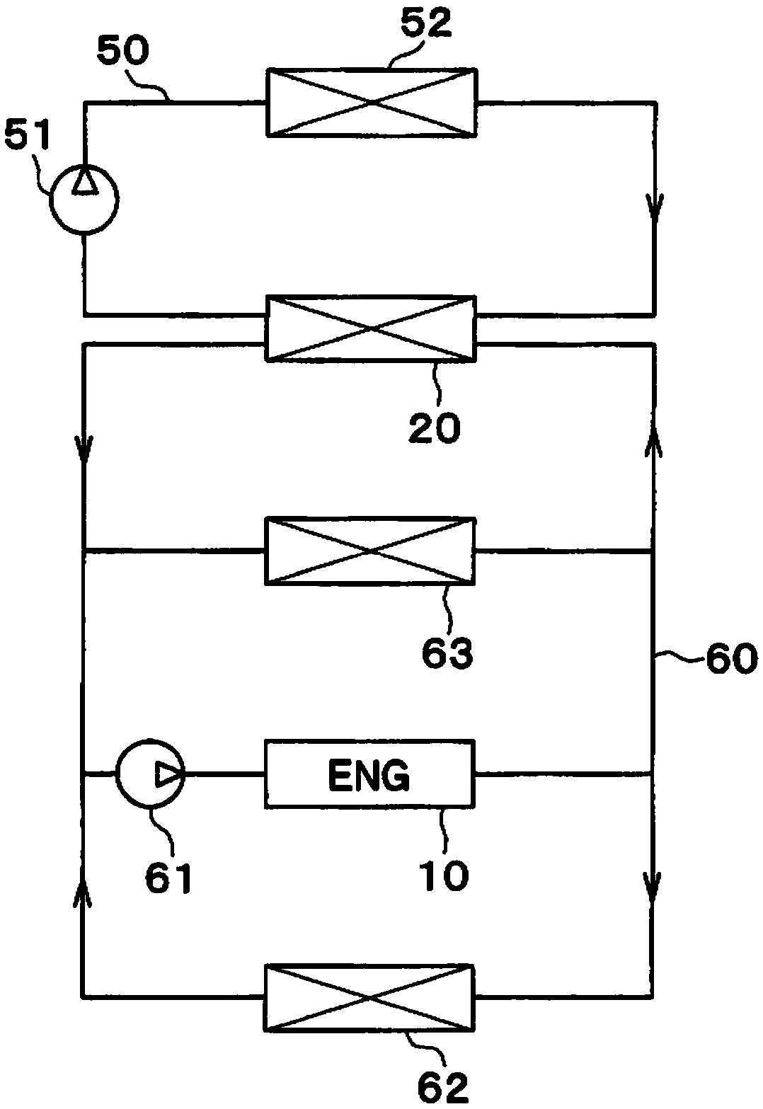
[0023] A first embodiment of the present invention will be described based on the drawings. The first embodiment will describe an example in which the intercooler of the present invention is applied to a charge air cooling system of a vehicle.

[0024] A not-shown supercharger for supercharging intake air and supplying it to the engine 10 is provided in an intake system of an engine (ie, an internal combustion engine) 10 of a vehicle. The supercharger is provided to compensate for the highest output of the engine 10 . That is, in the vehicle of the present embodiment, the engine 10 is reduced in exhaust gas for the purpose of improving fuel economy, and the supercharger compensates for the decrease in the maximum output accompanying the small exhaust gas reduction.

[0025] An intercooler 20 that cools engine intake air is provided on the downstream side of the intake air flow of the supercharger in the intake system. The intercooler 20 serves to improve the filling efficien...


PUM


Abstract

This intercooler is provided with a heat exchange unit (23) in which a flow path tube (21) and a fin (22) are arranged in a stacked manner and which performs heat exchange between a cooling medium inside the flow path tube and supercharged intake air outside the flow path tube. The cooling medium includes a first cooling medium and a second cooling medium having a higher temperature than the firstcooling medium. A first cooling medium flow path (25), in which the first cooling medium flows, and a second cooling medium flow path (26), in which the second cooling medium flows, are formed in theflow path tube. The second cooling medium flow path is disposed further upstream with respect to the supercharged intake air than the first cooling medium flow path. The second cooling medium flow path has a second U-turn portion (26d) in which the second cooling medium makes a U-turn. In the second cooling medium flow path, a downstream flow path (26f) which is downstream of the second U-turn portion is positioned further upstream in the supercharged intake air flow direction than an upstream flow path (26e) which is upstream of the second U-turn portion. Between the flow path tube and the fin, a heat exchange suppression portion (30) is provided in a region that corresponds to the most upstream portion of the downstream flow path in the supercharged intake air flow direction.

Description

[0001] Cross-reference to related applications [0002] This application is based on Japanese Patent Application No. 2016-024231 filed on February 11, 2016, the disclosure of which is incorporated herein by reference. technical field [0003] The present invention relates to an intercooler for cooling supercharged intake air pressurized by a supercharger. Background technique [0004] Conventionally, an intercooler is known that cools supercharged intake air by exchanging heat between supercharged air supercharged by a supercharger and supplied to an engine and two types of cooling water having different temperatures (for example, refer to Patent Documents). 1). The intercooler described in Patent Document 1 is configured such that the high-temperature cooling water flows in a U-turn on the upstream side in the flow direction of the supercharged intake air, and the low-temperature cooling water flows in a U-turn on the downstream side in the flow direction of the supercharg...

Claims


Application Information

Patent Timeline
Patent Type & Authority Applications(China)
IPC IPC(8): F02B29/04
CPCF02B29/0443F02B29/04Y02T10/12F01P2060/02F28D9/0056
Inventor 畔柳功原田真树川口雄史
Owner DENSO CORP
Why Eureka
Try Eureka