Airbag device

a technology for airbags and airbags, which is applied in the direction of pedestrian/occupant safety arrangements, vehicular safety arrangements, vehicle components, etc., to achieve the effect of smooth airbag inflation and little fear of gas leakag

Active Publication Date: 2020-04-28
TOYODA GOSEI CO LTD
View PDF11 Cites 6 Cited by
  • Summary
  • Abstract
  • Description
  • Claims
  • Application Information

AI Technical Summary

Benefits of technology

[0005]An object of the present invention is to provide an airbag device for a vehicle that is capable of inflating an airbag smoothly with little fear of gas leakage via a gap between an inflator and a retainer.
[0010]In the airbag device of the invention, the mounting base section of the retainer includes, between the second mounting means and the storing dent section and proximate to the storing dent section, the pressing section which is adapted to be brought into close contact with a predetermined circumferential area of the body of the inflator when the airbag device is secured to the member of the vehicle through the use of the first mounting means of the inflator. The pressing section is capable of preventing an inflation gas, which has exited the gas release section of the inflator and flown through a gap between the mounting base section and the body of the inflator, from further flowing towards the first mounting means of the inflator. Thus the airbag will inflate quickly with little fear of gas leakage despite the configuration that the first end region of the inflator provided with the first mounting means is disposed outside of the airbag. Moreover, a strong pressing by the pressing section will not occur until the first mounting means is fastened to the member of the vehicle. Accordingly, the pressing section will not hinder an insertion work of the body of the inflator into the holding section of the retainer.
[0011]Therefore, the airbag device of the invention is capable of inflating the airbag smoothly with little fear of gas leakage via a gap between the inflator and retainer.

Problems solved by technology

This configuration may cause a gas leakage via a gap between the holding section of the retainer and the inflator, and therefore some measures need to be taken against gas leakage.

Method used


Image

  • Airbag device
  • Airbag device
  • Airbag device

Examples


Embodiment Construction

[0038]Preferred embodiments of the present invention are described below with reference to the accompanying drawings. However, the invention is not limited to the embodiments disclosed herein. All modifications within the appended claims and equivalents relative thereto are intended to be encompassed in the scope of the claims.

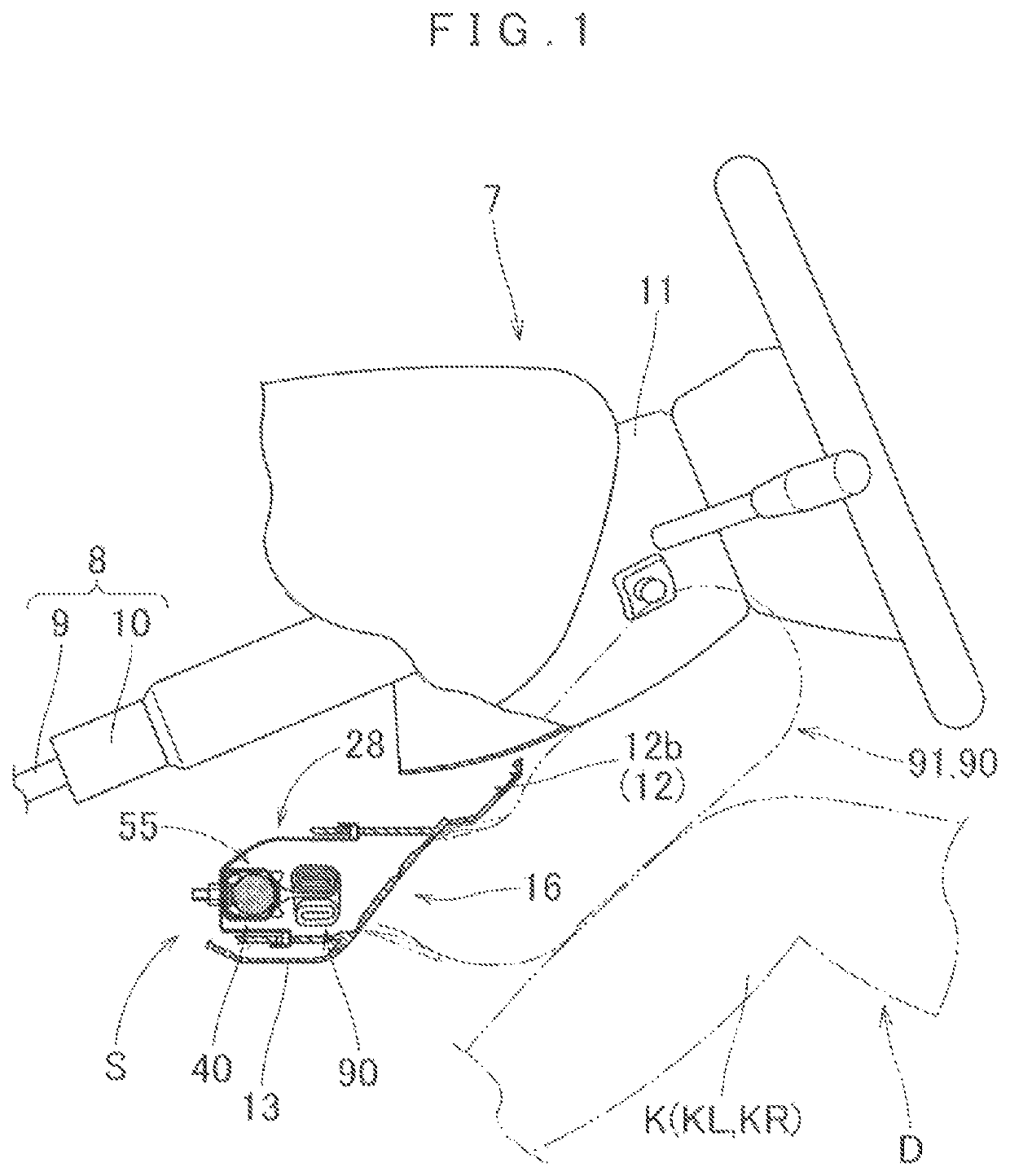
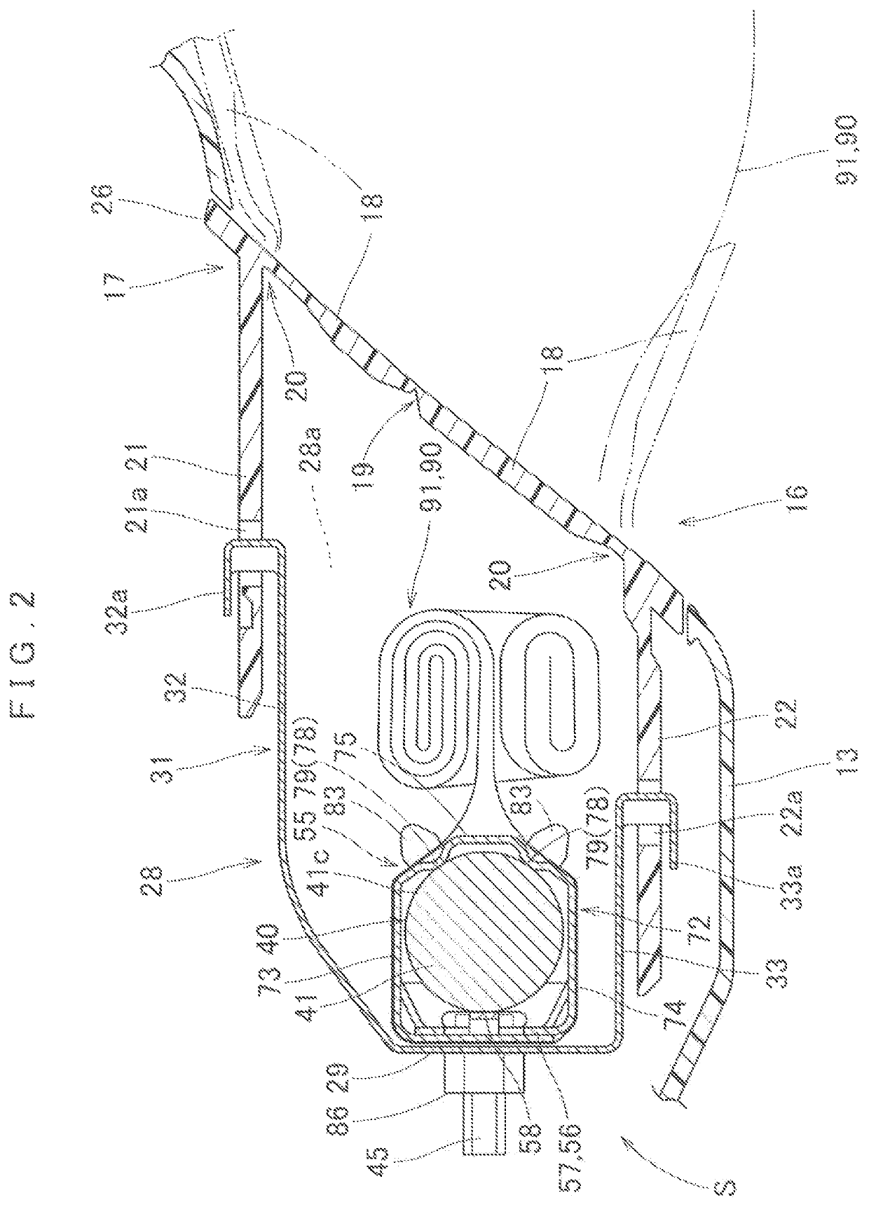
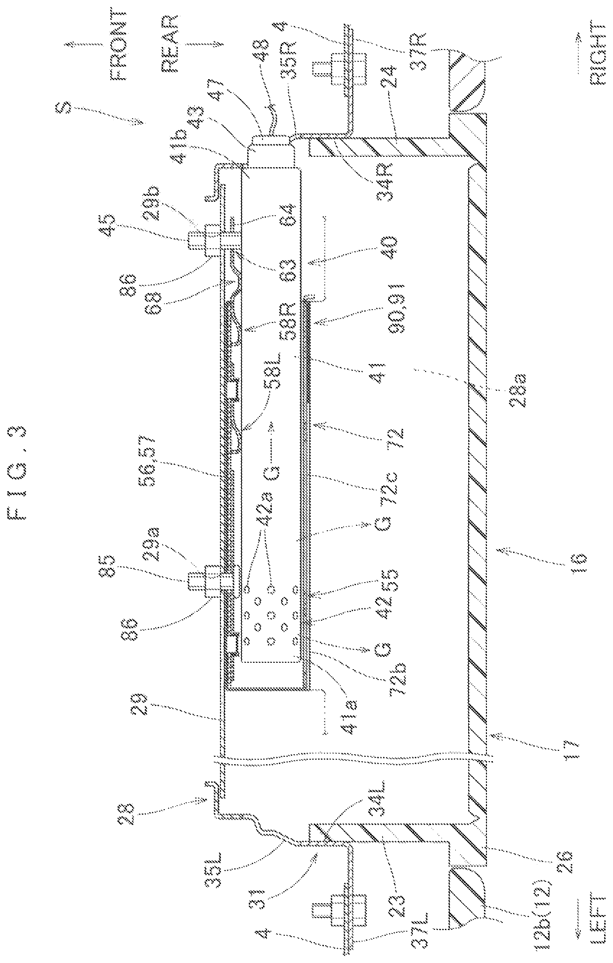
[0039]As shown in FIGS. 1 and 4, an airbag device S embodying the invention is mounted beneath a steering column 7, in front of a driver's seat of a vehicle, as a knee-protecting airbag device for protecting knees K (KL and KR) of a driver (as an occupant) D. Unless otherwise specified, up / down, left / right and front / rear directions in this specification are intended to refer to up / down, left / right and front / rear directions of the airbag device S as mounted on the vehicle.

[0040]The steering column 7 includes a column body 8 and a column cover 11 which covers an outer circumference of the column body 8. As shown in FIG. 1, the column body 8 includes a main shaft...


PUM


Abstract

A retainer and an inflator are disposed inside the airbag. The retainer includes a mounting base section, a holding section which extends from the mounting base section and receives and holds an inflator therein, and a second mounting means which protrudes from the mounting base perpendicularly. The inflator includes a cylindrical body provided with a gas release section and, a first mounting means protruding from a region of the body disposed outside the airbag. The retainer further includes a storing dent section which receives the first mounting means of the inflator so as to conform an orientation of the first means to that of the second mounting means and, a pressing section disposed proximate the storing dent section. The pressing section is brought into close contact with a circumferential area of the body of the inflator when the first mounting means of the inflator is secured to a vehicle body.

Description

CROSS REFERENCE TO RELATED APPLICATIONS[0001]The present application claims priority from Japanese Patent Application No. 2017-068788 of Shigemura, filed on Mar. 30, 2017, the entire disclosure of which is incorporated herein by reference.BACKGROUND OF THE INVENTION1. Field of the Invention[0002]The present invention relates to an airbag device which includes an airbag, an inflator for feeding the airbag with an inflation gas, and a retainer used to mount the airbag and inflator on the vehicle body structure.2. Description of Related Art[0003]JP 2014-73823 A discloses a known airbag device which includes an airbag, a generally cylindrical inflator for feeding the airbag with an inflation gas, and a retainer which holds the inflator and mounts the airbag and inflator on a vehicle body member. The inflator includes a fixing means at its first end portion in the axial direction. The fixing means is arranged to protrude in a direction generally perpendicular to the axial direction of th...

Claims


Application Information

Patent Timeline
Patent Type & Authority Patents(United States)
IPC IPC(8): B60R21/217B60R21/206B60R21/264B60R21/00B60R21/26B60R21/231
CPCB60R21/206B60R21/264B60R21/2171B60R2021/23169B60R2021/0051B60R2021/26076B60R21/217B60R21/261
Inventor SHIGEMURA, TAKASHI
Owner TOYODA GOSEI CO LTD
Why Eureka
Try Eureka