Snap cap in multi-component injection molding technology

a multi-component injection molding and snap cap technology, applied in the direction of transportation and packaging, closures with lifting/suspension means, other domestic articles, etc., can solve the problems of known click-clack caps and far only available in metal materials, and achieve the effect of expanding their applicability

Active Publication Date: 2020-09-08
KITTMANN ROLAND
View PDF81 Cites 5 Cited by
  • Summary
  • Abstract
  • Description
  • Claims
  • Application Information

AI Technical Summary

Benefits of technology

[0012]This is achieved according to the invention in that at least one expansion portion in the edge portion of the cover is made of a softer material than the remaining edge portion. The expansion portion elastically expands under tension and allows the edge portion to widen in the condition of concave front wall curvature, while the base material (i.e. a first material component) of the cover is otherwise stiff enough to maintain the angle in the transition region between the front wall and the edge portion constant. This enables the cover to flip over into the bistable state with the larger outer circumference.
[0013]Preferably, the expansion portion is formed together with the rest of the cover made in one piece in a multi-component injection molding process. For the expansion portion, a second material component is then injected which is softer and / or more elastic than the first material component used for the remaining cover. In order to further support the constant angle in the transitional area between the front wall and the edge portion, the cover in this transitional area can preferably have a higher material thickness of the harder (base) material component than in the main area of the front wall or be injection-molded from an even harder third material component. This leads to the particular advantage that the cover as a whole has a constant material thickness. A homogeneous thickness is not only visually appealing, but also reduces the number of steps and edges where debris is collected.
[0014]According to a particularly preferred embodiment, the front wall further comprises a handle member by which the front wall can be easily lifted and pressed by hand. This is particularly important when the closure element is not engaging from the outside as a cap on the opening to be closed, but engages as a lid from inside into the side wall of the opening to be closed. In the closed state, the lid could then no longer be removed from the opening without a suitable handle member. The handle member provides the further advantage that it reinforces the center region of the front wall, which should remain as rigid as possible in its horizontal orientation during the folding process between the convex and concave positions.

Problems solved by technology

The known click-clack caps, however, suffer from the disadvantage that they are so far only available in metal material, especially tinplate.

Method used


Image

  • Snap cap in multi-component injection molding technology
  • Snap cap in multi-component injection molding technology
  • Snap cap in multi-component injection molding technology

Examples


first embodiment

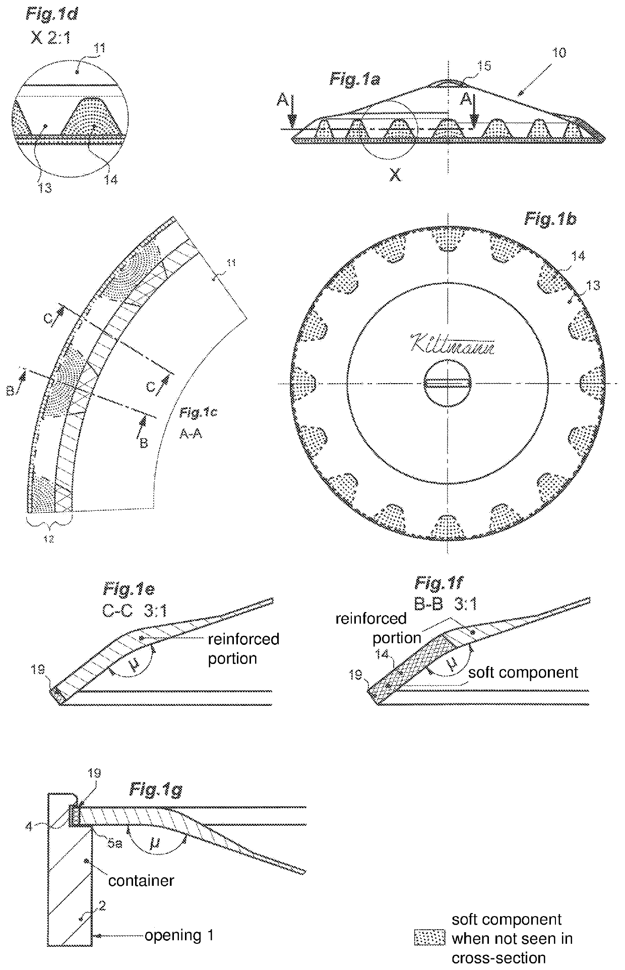
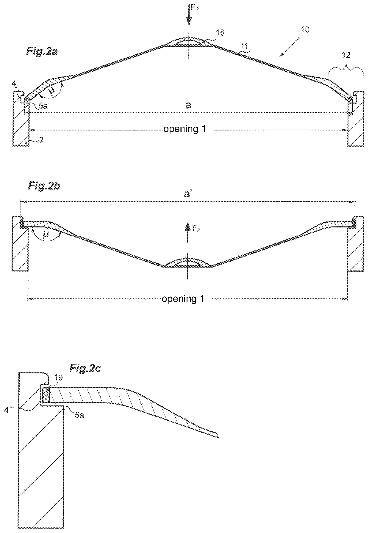
[0054]FIGS. 2a to 2c show the operation of a closure system according to the invention, in which the lid 10 of the first embodiment for closing the opening 1 is used. The wall portion 2 of the opening 1 to be closed has an annular groove 4 inside, in which the lid 10 is to engage, and which has a shoulder 5a at its lower edge.

[0055]When introducing the lid 10 from above into the opening 1, the edge portion 12 will abut with the latching ring 19 against the shoulder 5a. As a result, the user knows that he has reached the intended axial end position of the lid 10 for locking. If the user now presses the front wall 11 down (best by a force F1 on the handle member 15 vertically downwards), the front wall 11 switches from its convex bistable state shown in FIG. 2a in its concave bistable state shown in FIG. 2b. Due to the stiffness of the lid material in the transition region between the front wall 11 and the edge portion 12, which is preferably supported by material thickening, the angl...

second embodiment

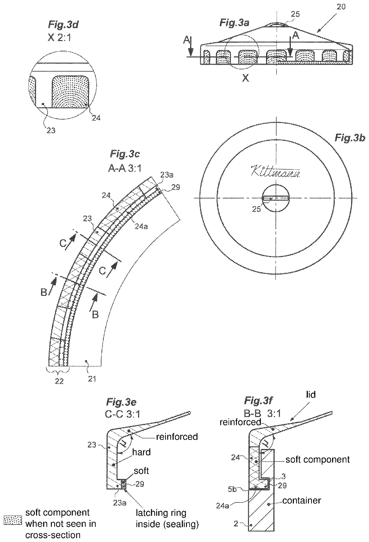
[0059]In the second embodiment shown in FIGS. 3 and 4, the cover according to the invention is no longer a lid engaging from the inside into the opening to be closed, but formed as a cap 20 embracing the opening 1 to be closed from the outside. FIGS. 3a to 3f all show the cap 20 in its convex position cambered outwardly (i.e. opposite to the direction of attachment), i.e. its closed position. It is additionally shown in FIG. 3f how in this position, a latching into the opening wall 2 to be closed is possible, which will be explained in more detail in FIGS. 4a to 4c.

[0060]As with the lid 10 in the first embodiment, the cap 20 has a substantially circular or disc-shaped front wall 21, which continues into an annular edge portion 22. In the transition region between the front wall 21 and the edge portion 22, the material thickens again, as can be seen in FIGS. 3e and 3f, to ensure that the angle μ (not drawn in FIGS. 3e and 3f but shown in FIG. 4a) remains constant also in the concave...


PUM

PropertyMeasurementUnit
constant angleaaaaaaaaaa

Abstract

A cover includes a bistable flap mechanism made of a plastic with at least two material components. The cover can be produced in one piece in a multi-component injection molding technique. At a transitional area between a front wall and an edge portion, the plastic is sufficiently stiff (preferably due to greater material thickness) to ensure that an angle μ enclosed in the transitional area from the side wall to the edge portion remains constant in both bistable states. Expansion portions provided in the edge portion ensure that the outer circumference of the edge portion can increase / decrease from one bistable state to the other bistable state. A closing system including the cover is also provided.

Description

BACKGROUND OF THE INVENTIONField of the Invention[0001]Since the 1920s, it has been known to make small round metal cans with a snap closure that can be opened and closed in bistable fashion by pressure on its front wall. Such snap closures are described, for example, in the patent document DE 442 634 C and consist of a circular front wall, which is deformable in a bistable manner between a convex and a concave state, and a peripheral edge portion of crenel-like spread fingers, which are designed to embrace in the closure position an embossment formed on the outer edge of the metal can.[0002]Such metal cans of tinplate are sold, for example, by the company Hoffmann Neopac as merchandising products under the brands Klick-Klack® Klipp-Klapp®. A more detailed description of the cans can be found, for example, in the patent document EP 2 291 315 B1.[0003]In the prior art, it has not yet been recognized or at least not described, that for the functioning of the snap mechanism of the abov...

Claims


Application Information

Patent Timeline
Patent Type & Authority Patents(United States)
IPC IPC(8): B65D43/02B65D43/06B65D39/02B29C45/16B65D51/24B29K75/00B29K77/00B29K509/08B29L31/56
CPCB65D51/242B65D43/0212B65D43/0202B65D43/021B29C45/1676B29K2075/00B65D2543/00296B65D2543/00092B29K2077/00B65D2543/0049B65D2543/0099B65D2543/0037B65D2543/00314B29L2031/565B65D2543/00935B65D2543/00537B65D2543/00851B29K2509/08B65D2543/00351
Inventor KITTMANN, ROLAND
Owner KITTMANN ROLAND
Why Eureka
Try Eureka