Roof installation support fixing device and roof installation system

a technology for fixing devices and roofs, applied in the direction of heat collector mounting/support, photovoltaics, sustainable buildings, etc., can solve the problems of comparatively complex, correspondingly expensive manufacture, and the solution is also comparatively complex, and achieves reliable fixing, constant material thickness, and simple manner.

Active Publication Date: 2017-06-13
SIKA TECH AG
View PDF14 Cites 0 Cited by
  • Summary
  • Abstract
  • Description
  • Claims
  • Application Information

AI Technical Summary

Benefits of technology

[0005]The object of the invention is to indicate an improved fastener for a roof installation support and a correspondingly improved roof installation system that offer increased strength and reliability and can be economically produced and installed.
[0010]It is provided in one embodiment that the second shank of the “U” is connected stiffly, in particular integrally to the base plate section. Furthermore, it is provided in terms of design that stiffening ribs running transversely to the longitudinal extent of the first partial section of the base plate section are formed in the throat between the profile section and the base plate section where the second shank of the “U” is connected to the base plate section. On the whole, a configuration of the fastener that is preferably constructed in such a manner ensures sufficient stiffness and a stable position of the fastened support on the base, while at the same time ensuring sufficient ease of installation and a durable fastening on the base.
[0013]One length of the profile section is preferably (on average) at least 3 times, preferably at least 5 times as large as a maximal extension in one direction perpendicular to the longitudinal direction of the profile section. As a result, the fastener can create an especially reliable fastening. Alternatively or additionally, the profile section can have a constant material thickness. As a result, the profile section can be produced in an especially simple manner and can nevertheless ensure a secure connection.
[0014]A material thickness of the profile section is (on average) preferably greater (at least 1.2 times or at least 1.5 times greater) than a material thickness of the baseplate section. Alternatively or additionally, an E modulus of the profile section can (on average) be greater than an E modulus of a material of the baseplate section (at least 1.2 times or at least 1.5 times or at least twice as great). As a result of these measures, an increased stiffness of the profile section relative to the baseplate section can be achieved in a simple manner.
[0015]In a preferred embodiment, a (average) height of the profile section is greater than a (average) width of the profile section (preferably at least 1.5 times greater, further preferably at least 2 times greater and even more preferably at least 3 times greater). The direction of the height is perpendicular to the surface of the baseplate section. The direction of the width is perpendicular to the direction of the height and the longitudinal direction provided by the extension of the profile section. As a result, a longitudinal edge of a roof installation support can be accommodated especially securely in the profile section, wherein the different degrees of stiffness can be utilized synergistically by the base body section and the profile section. On the whole, a reliable fastening can be achieved with simple measures. If the profile section is a U profile section (as described further above), the second shank of the “U” opposite the first shank can be larger than a connecting section between the two shanks, in particular at least 1.5 times, preferably at least 2 times, and even more preferably at least 3 times as large. In the case (as described above) of a U-shaped design of the profile section, the height of the profile section is defined by the second shank opposite the first shank. A width is defined by the connecting section between the two shanks.
[0017]In a preferred embodiment of the roof installation system, said system comprises at least one first and one second (separate from the first) fastener, wherein the first fastener is provided for attaching a first longitudinal edge of the roof installation support and the second fastener is provided for attaching a second longitudinal edge of the roof installation support. In addition, (at least) two first fasteners and (at least) two second fasteners are preferably provided. Therefore, according to a general concept of the present invention, a plurality of (separate) fasteners that are associated with a (respective) roof installation support are provided within a roof installation system. As a result, in combination with the flexible base plate section and the comparatively stiff profile section, even given uneven bases, a reliable fastening of the roof installation support can be synergistically achieved.

Problems solved by technology

On the whole, the structure according to WO 2012 / 004542 A2 is comparatively complex, which is associated with a correspondingly expensive manufacture.
As a result, this solution is also comparatively complex and is associated with high production and installation cost.

Method used


Image

  • Roof installation support fixing device and roof installation system
  • Roof installation support fixing device and roof installation system
  • Roof installation support fixing device and roof installation system

Examples


Embodiment Construction

[0005]The object of the invention is to indicate an improved fastener for a roof installation support and a correspondingly improved roof installation system that offer increased strength and reliability and can be economically produced and installed.

[0006]This object is attained by a fastener having the features of Claim 1 and by a roof installation system having the features of Claim 11. Advantageous further developments of the concept of the invention are the subject matter of the respective dependent claims.

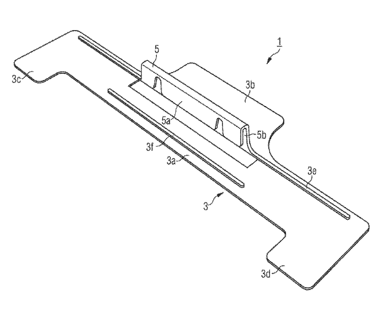
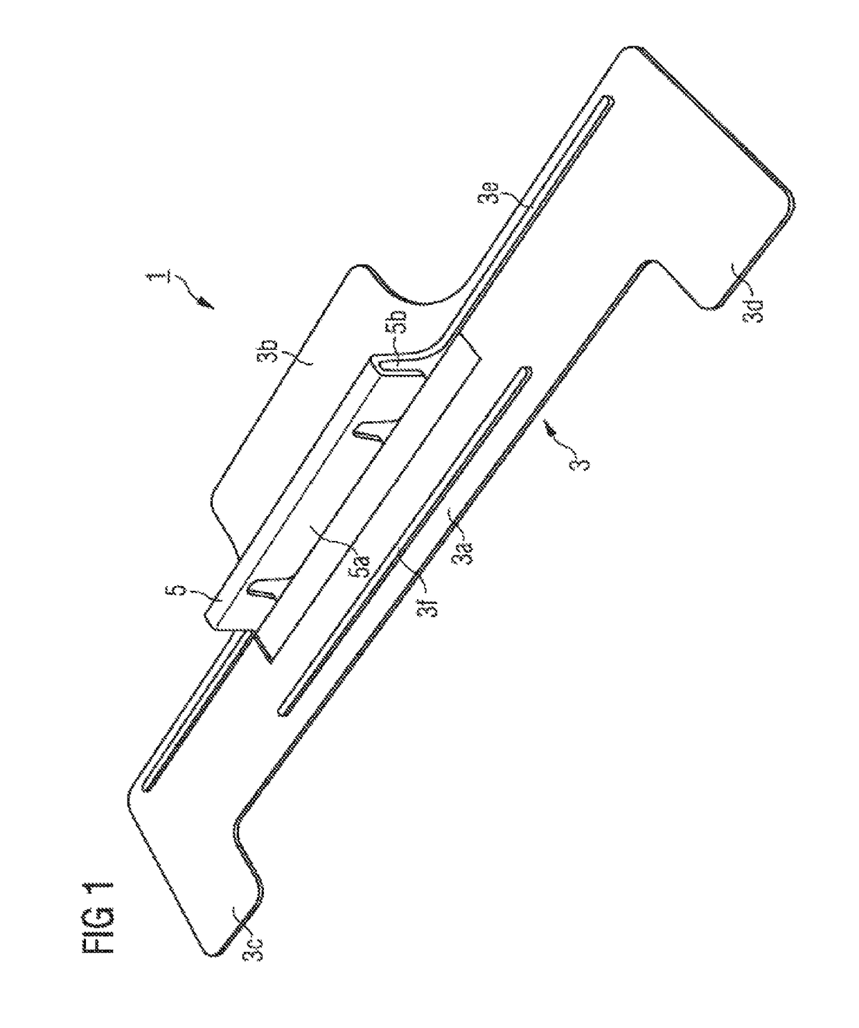
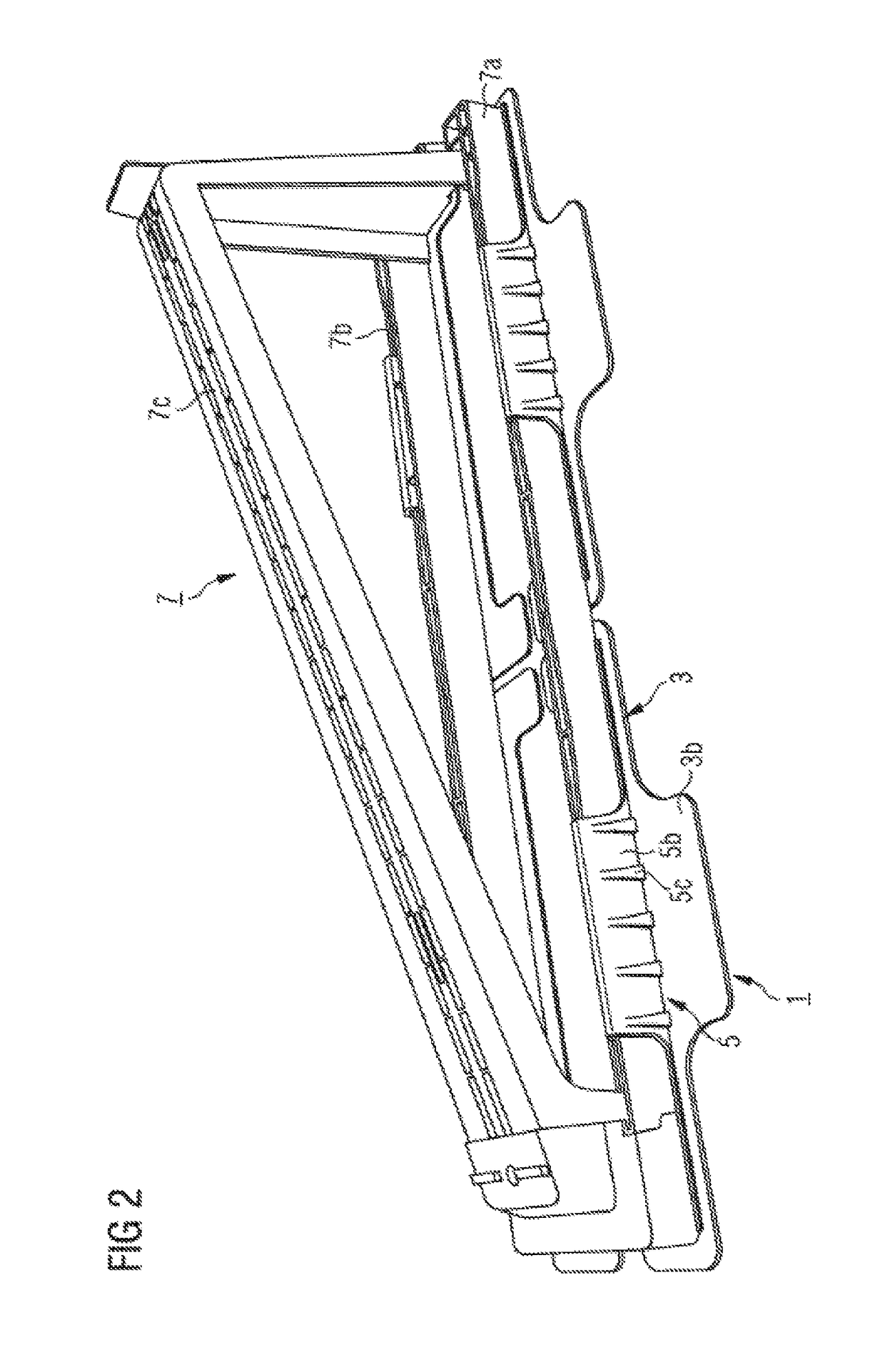
[0007]One concept of the invention consists in constructing the fastener with two sections that are defined differently in terms of function and as regards significant mechanical properties: On the one hand, a baseplate section is provided for attachment to the base, which baseplate section has a sufficiently large surface and a certain flexibility for adapting to a (slightly) uneven base. On the other hand, a (rather) stiff section is provided for securely fixing the profile...


PUM


Abstract

A fastener for a roof installation support, in particular for a support of a solar technology system, comprising an at least sectionally flexible baseplate section and a substantially stiff profile section rising up from the baseplate section, which profile section is constructed to surround and positively fix a profile section of the roof installation support.

Description

TECHNICAL FIELD[0001]The invention relates to a fastener for a roof installation support, in particular a support for a solar technology plant. It further relates to a roof installation system, in particular for a solar technology system.PRIOR ART[0002]Solar technology systems, including photovoltaic systems and solar collectors are installed on house roofs using special roof installation systems which are designed to avoid as much as possible penetrating the roof covering by auxiliary installation means.[0003]It is important, especially in the case of flat roofs whose seal is produced by plastic sealing webs (KDB), to avoid a penetration of the roof seal by the support or fastening means of the roof installation system. EP 2 418 438 A2 discloses a support for a roof installation system for photovoltaic systems, which support can be connected by means of flexible fastening strips to a plastic sealing web without penetration thereof, by welding or adhesive fastening.[0004]A fastener ...

Claims


Application Information

Patent Timeline
Patent Type & Authority Patents(United States)
IPC IPC(8): H02S20/23H02S20/22E04B1/41F24J2/52E04B1/38
CPCH02S20/22E04B1/40F24J2/523F24J2/525E04B2001/405Y02B10/10Y02B10/20Y02E10/47F24S25/10F24S25/617Y02E10/50E04B1/388E04B2001/389
Inventor BLEIBLER, ALEXANDERHUBSCHER, PETERMEIER, HEINZROHRER, HANS
Owner SIKA TECH AG
Why Eureka
Try Eureka