Cutting section for a drill bit

Inactive Publication Date: 2021-03-18
HILTI AG
View PDF0 Cites 0 Cited by
  • Summary
  • Abstract
  • Description
  • Claims
  • Application Information

AI Technical Summary

Benefits of technology

The present invention aims to improve the functionality of a cutting section during drilling by enhancing the transmission of force, torque, and tensile loadings during removal of a jammed drill bit. Additionally, the manufacturing outlay for the production of a cutting section is intended to be reduced. The second formed sheet metal part has interlocking elements that connect in an interlocking manner, which prevents heat from entering the second open tubular element and reducing stresses.

Problems solved by technology

Disadvantages of the known “Hilti DD X-CM” cutting sections are the high outlay on production due to the turning of the annular stop shoulder and the milling of the slot-shaped recesses.
In addition, the choice of material for the ring section and the outer push element is limited.

Method used


Image

  • Cutting section for a drill bit
  • Cutting section for a drill bit
  • Cutting section for a drill bit

Examples


Embodiment Construction

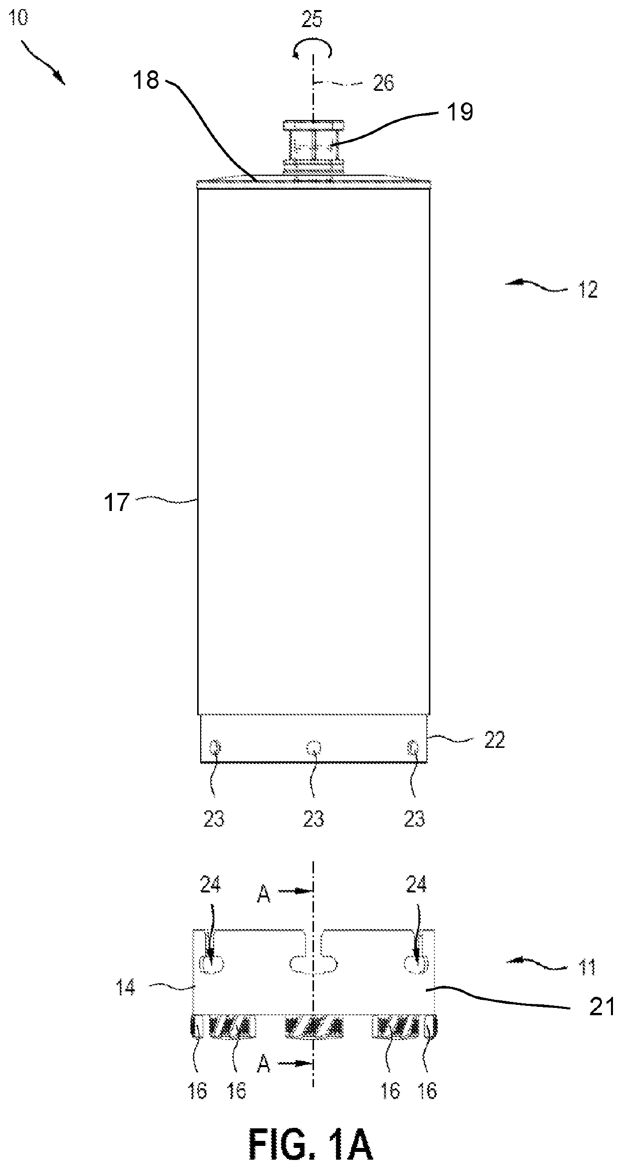
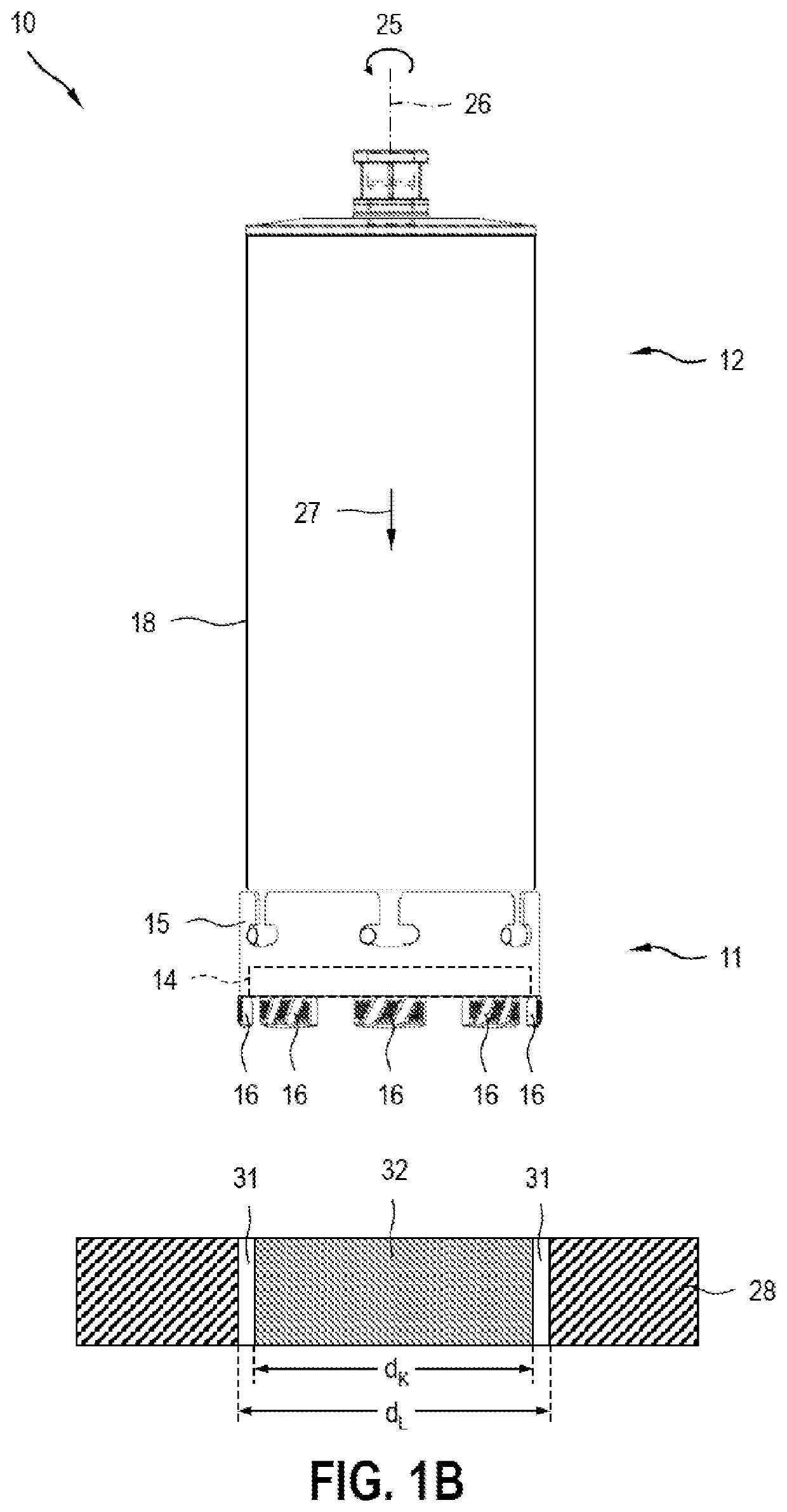
[0029]FIGS. 1A and 1B show a drill bit 10 which comprises a cutting section 11 according to the invention and a drill shaft section 12, wherein the cutting section 11 and the drill shaft section 12 are connectable via a releasable connecting device 13. In this case, FIG. 1A shows the cutting section 11 and drill shaft section 12 in an unconnected state of the drill bit, and FIG. 1B shows the cutting section 11 and drill shaft section 12 in a connected state of the drill bit.

[0030]The cutting section 11 comprises a first closed tubular element 14, a second closed tubular element 15 and a plurality of drill segments 16 which are connected to the first closed tubular element 14 and to the second closed tubular element 15. The drill segments 16 are connected to the first closed tubular element 14 and to the second closed tubular element 15, wherein the first and second tubular elements 14, 15 are likewise connected to each other in the region of the connection. When required, the first ...


PUM

PropertyMeasurementUnit
Timeaaaaaaaaaa
Heightaaaaaaaaaa

Abstract

A cutting section (11) which is connectable to a drill shaft section via a releasable connecting device. The cutting section includes a first closed tubular element (14) which is in the form of a first hollow cylinder, a second closed tubular element (15) which is in the form of a second hollow cylinder, and one or more drill segments (16) which are connected to the first closed tubular element (14) and to the second closed tubular element (15).

Description

TECHNICAL FIELD[0001]The present invention relates to a cutting section for a drill bit wherein the cutting section is connectable to the drill bit via a releasable connection.BACKGROUND[0002]WO 2014 / 096359 A1 discloses a cutting section for a drill bit, which cutting section is connectable to a drill shaft section of the drill bit via a releasable connecting device. The releasable connecting device is designed here as a combined push and twist connection. A “push and twist connection” refers to releasable connections between a first and a second connecting element, said connecting elements forming a push connection in one direction and being additionally connected via a twist connection. The cutting section comprises one or more drill segments, a ring section, an outer push element and an annular stop shoulder at the transition from the ring section to the outer push element.[0003]Cutting sections which are connectable with a combined push and twist connection are sold under the pr...

Claims


Application Information

Patent Timeline
IPC IPC(8): B23B51/04
CPCB23B51/0473B28D1/041B23B51/0461B23B51/0467
Inventor SCHROEDER, FLORIANDOMANI, GUENTERRONG, PINGYAN
Owner HILTI AG
Why Eureka
Try Eureka