
Housing element for an intermediate turbine housing

a technology of housing element and turbine housing, which is applied in the manufacture of engines, mechanical equipment, machines/engines, etc., can solve the problems of high component weight and higher specific fuel consumption of gas turbines in operation, and achieve the effect of improving the housing elemen

Active Publication Date: 2019-11-05
MTU AERO ENGINES GMBH
View PDF13 Cites 0 Cited by
  • Summary
  • Abstract
  • Description
  • Claims
  • Application Information

AI Technical Summary

Benefits of technology

[0005]It is an object of the present invention to improve a housing element in a way that makes it possible to overcome the above disadvantages.
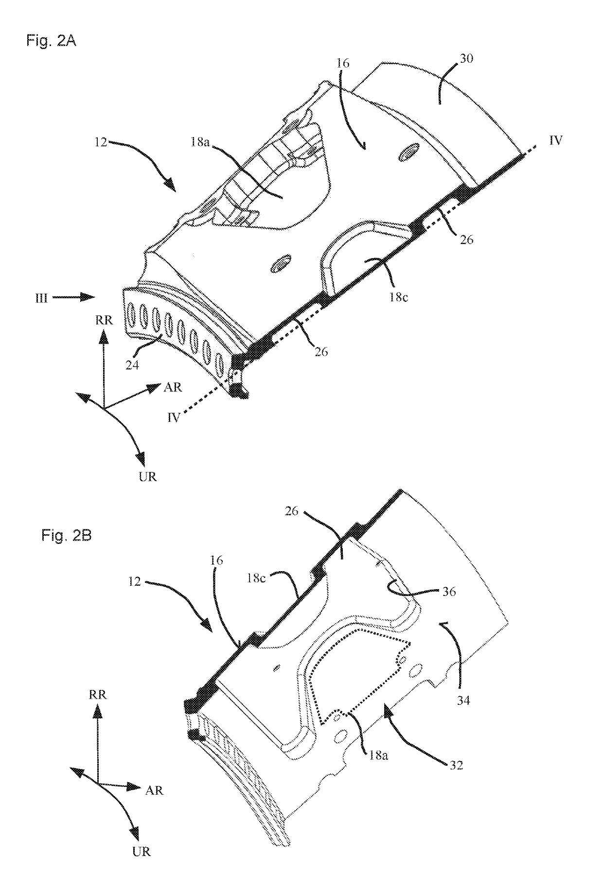
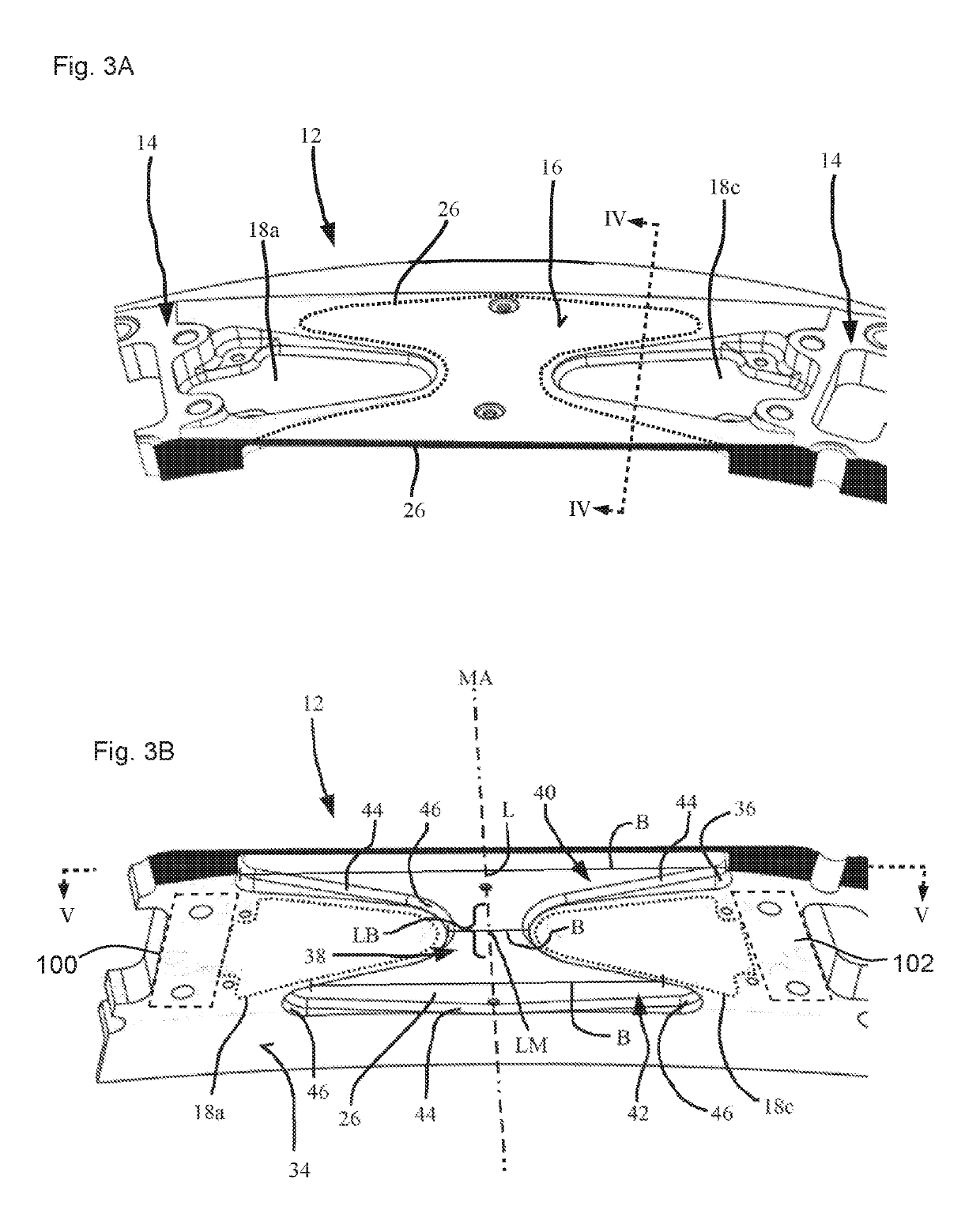
[0007]Such a recess reduces the component weight of the housing element while, at the same time, stiffness is maintained as the radially outer contour having the depressions is unchanged. The inventors discovered that there is no need for a substantially constant material thickness in those regions where no depressions are provided radially outwardly. Rather, there are regions where a reduced material thickness suffices without significantly adversely affecting the requisite stiffness of the housing element.
[0010]Preferably at least 30%, more preferably at least 50%, even more preferably at least 70% of the essentially planar housing element is formed by regions where there is either a recess on the radial inner side or a depression on the radial outer side of the housing element. In other words, if one imagined piercing through the housing element in the radial direction relative to the machine axis of the gas turbine, there is a probability of preferably 30%, more preferably of at least 50%, even more preferably of at least 70% of a region being pierced through where the housing element has either a recess on the radial inner side or a depression on the radial outer side. This makes possible a relatively thin and thus weight-optimized design of the housing element; similarly to reinforcing ribs, a substantial stiffness of the housing element being achieved by the reinforcing regions between the regions where the housing element has either a recess on the radial inner side or a depression on the radial outer side.
[0012]In this regard, it is also provided that the circumferential contour of the recess include a plurality of contour portions that merge into one another, the contour portions having a linear or arcuate form. The arcuate contour portions may thereby be designed to be circular arc-shaped, parabolic-shaped or hyperbolic-shaped, allowing a favorable configuration of the contour portions, respectively of the entire circumferential contour for the stress profile.

Problems solved by technology

With regard to achieving a more efficient operation of gas turbines, in particular aircraft gas turbines, it was recognized that the housing elements have a high component weight, which leads to higher levels of specific fuel consumption of the gas turbine in operation.

Method used


Image

  • Housing element for an intermediate turbine housing
  • Housing element for an intermediate turbine housing
  • Housing element for an intermediate turbine housing

Examples


Embodiment Construction

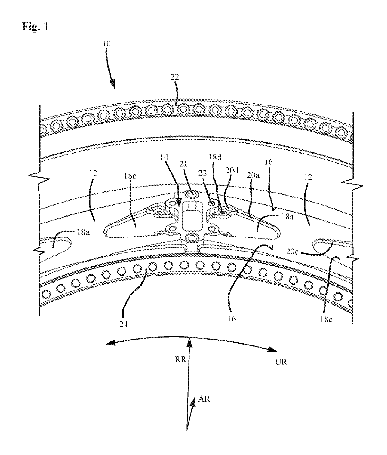
[0024]FIG. 1 shows a simplified, perspective detail view of an intermediate turbine housing 10 having two planar housing elements 12. The two housing elements 12 are each shown only partially and extend in circumferential direction UR, starting from a connection region 14, where housing elements 12 are joined to a strut that extends inwardly (See FIG. 3B), starting from connection region 14, essentially in radial direction RR. A plurality of such struts are spaced in circumferential direction UR of intermediate turbine housing 10. A housing element 12 is provided in each case between two such struts, respectively between two connection regions 14. AR characterizes the axial direction of the intermediate turbine housing.

[0025]The directional indications “axial,”“radial,” and “circumferential” are always relative to the machine axis of the gas turbine, unless otherwise explicitly or implicitly derived from the context.

[0026]Extending from an outer surface 16, housing element 12 has a ...


PUM


Abstract

A housing element (12) for an intermediate turbine housing of a gas turbine, in particular an aircraft gas turbine; the housing element (12) being installable or installed in the intermediate turbine housing radially outwardly, in each case between a plurality of circumferentially spaced struts; the housing element (12) having a planar form and, relative to the radial outer side (16) thereof, a plurality of depressions (18c), is provided. On the radial inner side (32, 34) thereof, the housing element (12) has at least one recess (26) that is configured outside of the regions in which depressions (18c) are formed on the radial outer side (16).

Description

[0001]This claims the benefit of German Patent Application DE 10 2016 201 863.9, filed Feb. 8, 2016 and hereby incorporated by reference herein.[0002]The present invention relates to a housing element for an intermediate turbine housing of a gas turbine, in particular an aircraft gas turbine; the housing element being installable or installed in the intermediate turbine housing radially outwardly between a plurality of circumferentially spaced struts; the housing element having a planar form and, relative to the radial outer side thereof, a plurality of depressions.BACKGROUND[0003]With the assistance of the depressions, such housing elements provide a uniform as possible stress distribution in each instance between two struts, over a cross-sectional profile having a constant surface area over the circumference of an intermediate turbine housing. The required stiffness is thereby mainly determined by the radially outer contour having the plurality of depressions. The depressions may ...

Claims


Application Information

Patent Timeline
Patent Type & Authority Patents(United States)
IPC IPC(8): F01D25/28F01D25/24F01D25/16
CPCF01D25/162F01D25/28F01D25/24F05D2260/15F05D2250/72F05D2220/323Y02T50/671Y02T50/60
Inventor BICKMEIER, WOLFGANGKUFNER, PETRA
Owner MTU AERO ENGINES GMBH
Learn More