

Gas turbine engine component incorporating a seal slot
a gas turbine engine and seal slot technology, applied in the field of turbine engines, can solve the problems of increasing the weight of the airframe, generating substantial centrifugal loads, and directly affecting the performance and efficiency of the engine and the aircraft it powers, and achieve the effect of reducing the weight of the componen
- Summary
- Abstract
- Description
- Claims
- Application Information
AI Technical Summary
Benefits of technology
Problems solved by technology
Method used
Image

Examples
Embodiment Construction
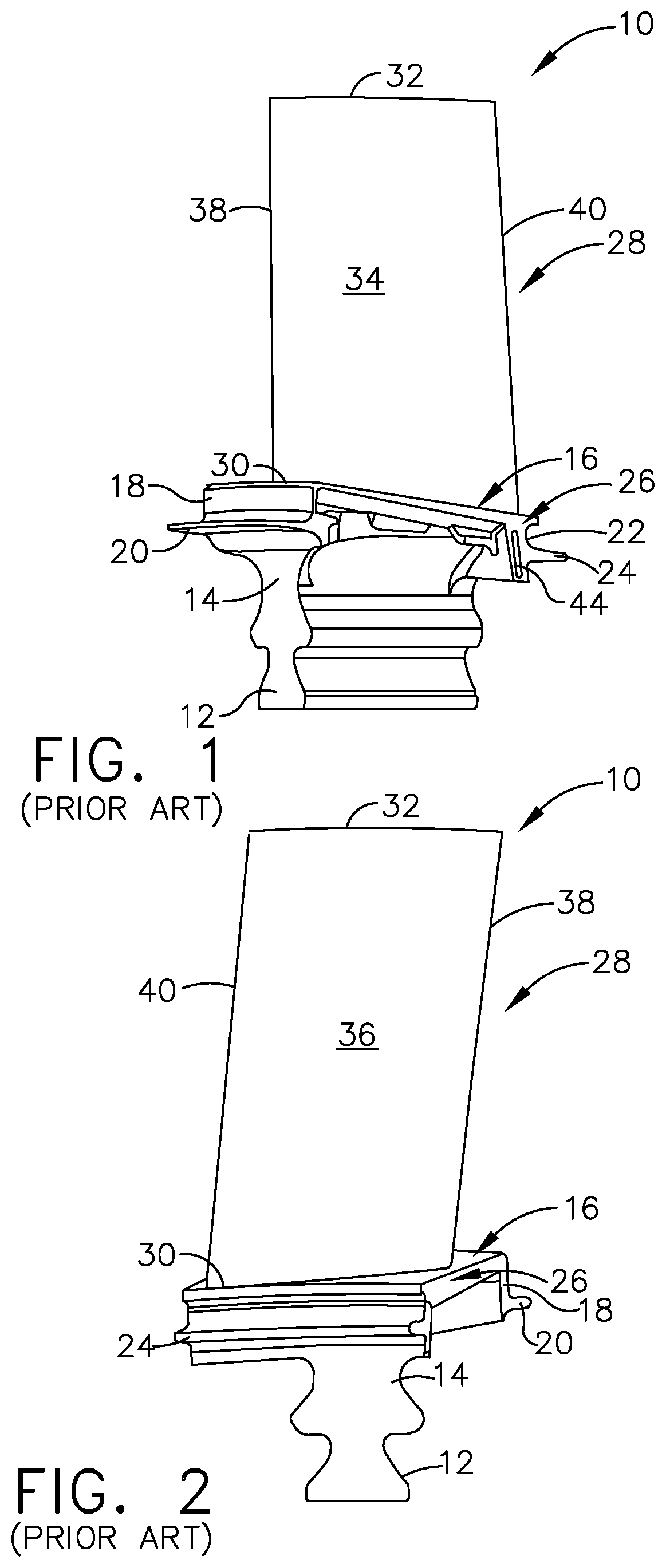
[0027]The concept described herein relates to the modification of the design of a turbine engine component incorporating one or more slots for a spline seal by providing a locating structure, e.g. a “receptacle” configured to retain the spline seal in a desired position, and by removing excess material not required to perform that function in order to reduce the mass of turbine component.
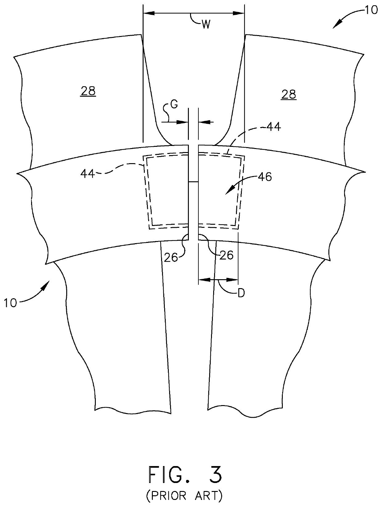
[0028]Now, referring to the drawings wherein identical reference numerals denote the same elements throughout the various views, FIG. 1 depicts an exemplary turbine blade 10. The turbine blade 10 is just one example of numerous components within a gas turbine engine or similar turbomachinery apparatus in which an annular assembly is built up from a ring of individual components, each defining an arc segment. Such components could be located anywhere in the engine and are not limited to a particular module. Non-limiting examples of such components include the inner or outer bands of stationary airfoi...
PUM
 Abstract
Description
Claims
Application Information