Heat exchanger system having manifolds structurally integrated with a duct

a heat exchanger and manifold technology, which is applied in the direction of heat exchanger casings, light and heating apparatus, laminated elements, etc., can solve the problems of saving a substantial amount of weight, and achieve the reduction of the total component weight, the part count and complexity of the heat exchanger system, and the pressure drop through the inlet manifold.

Active Publication Date: 2008-07-03
GENERAL ELECTRIC CO
View PDF9 Cites 6 Cited by
  • Summary
  • Abstract
  • Description
  • Claims
  • Application Information

AI Technical Summary

Benefits of technology

[0016]The present approach provides a number of important advantages over alternative possible design approaches for the heat exchanger system. The pressure drop through the inlet manifold, the heat exchanger, and the outlet manifold is reduced, as compared with alternative approaches. The total component weight is reduced. Part count and complexity of the heat exchanger system are reduced, the amount of tooling and its cost and complexity are reduced, and engine build time is reduced, all of which are significant considerations in manufacturing. The overall manufacturing cost is thereby reduced. Bypass air leakage is eliminated. Part wear is reduced, and maintainability is improved due to the reduction in part wear, the reduction in part count, and the elimination of joint leakage. The size and envelope of the manifolding are reduced as compared with alternative approaches such as piped gas-flow systems for the hot gas. The latter is an important consideration for the modern gas turbine engine, inasmuch as space must be available within the overall engine envelope for a large number of systems of different types, and reducing the size and envelope of each component aids in finding space for the others.

Problems solved by technology

That is, the duct wall forms a portion of the walls of the manifolds and of the heat exchanger, thereby saving a substantial amount of weight.

Method used


Image

  • Heat exchanger system having manifolds structurally integrated with a duct
  • Heat exchanger system having manifolds structurally integrated with a duct
  • Heat exchanger system having manifolds structurally integrated with a duct

Examples


Embodiment Construction

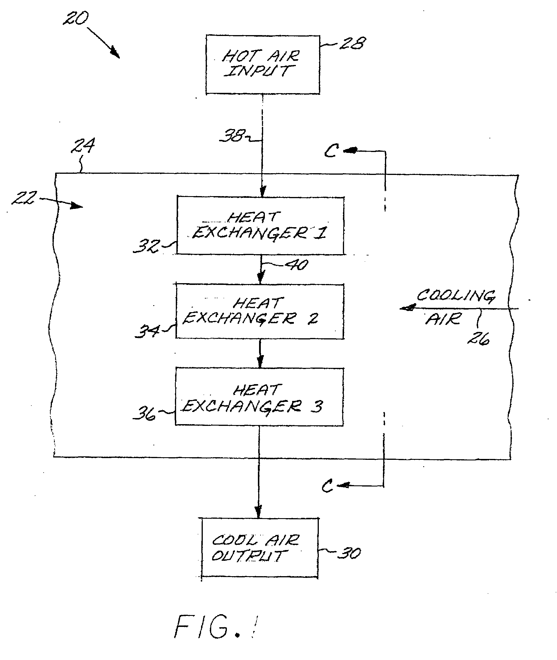
[0023]As used herein, a “fluid” may be a gas or a liquid. The present approach is not limited by the types of fluids that are used. In the preferred application, the cooling fluid is air, and the cooled fluid is air. The present approach may be used for other types of liquid and gaseous fluids, where the cooled fluid and the cooling fluid are the same fluids or different fluids, and may be used either to heat or cool various fluids. Other examples of the cooled fluid and the cooling fluid include hydraulic fluid, fuel, oil, and combustion gas.

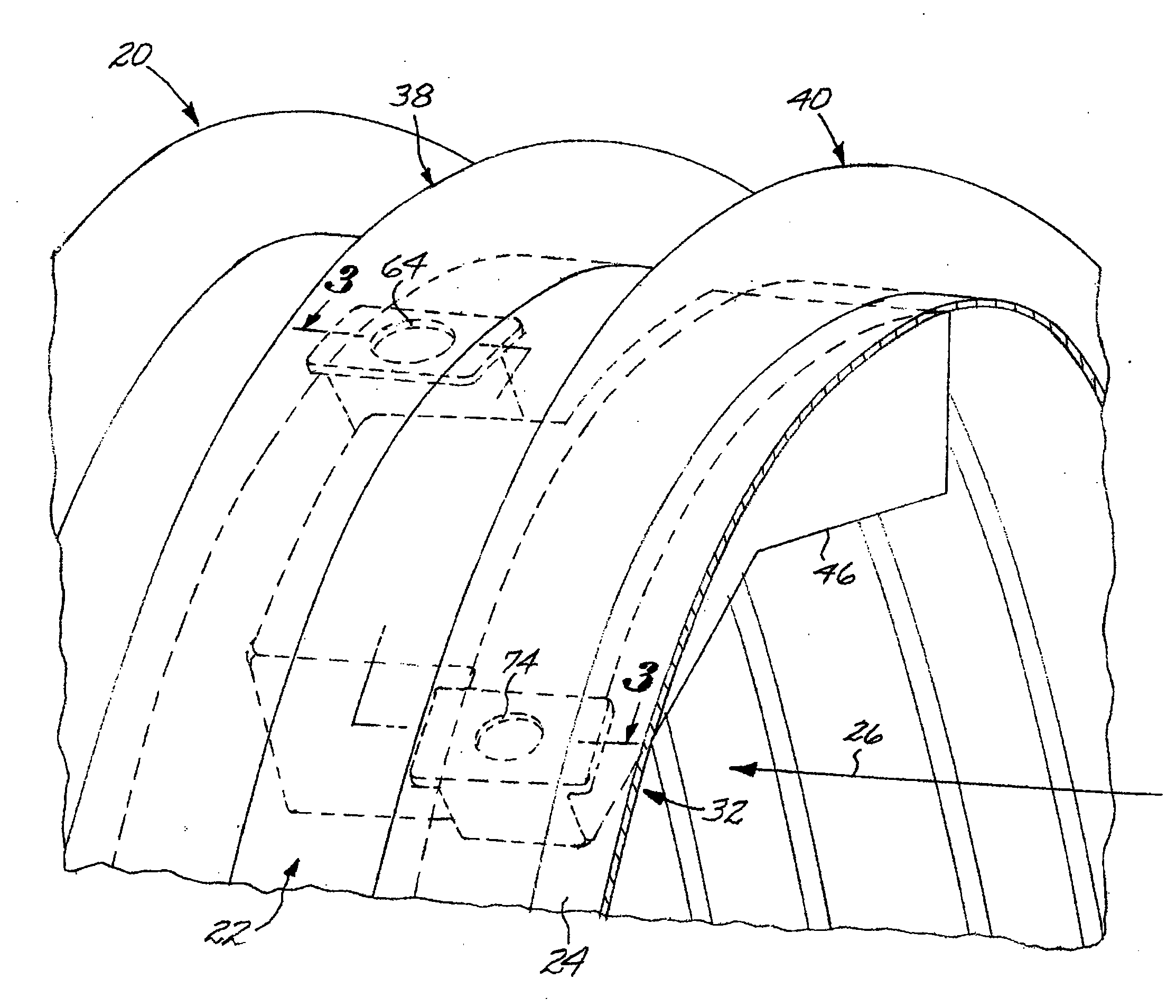
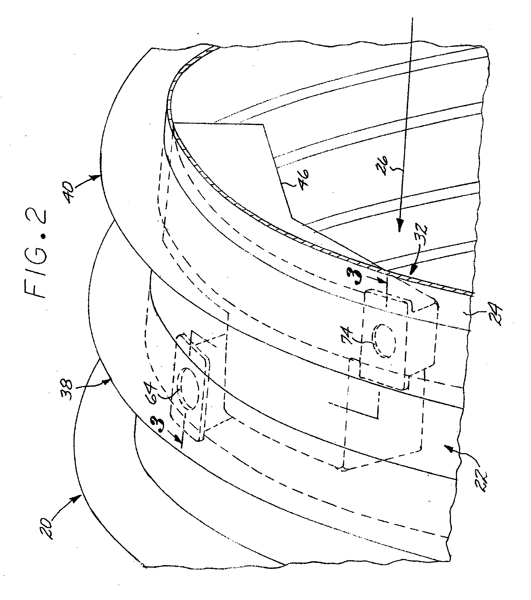
[0024]FIG. 1 depicts a heat exchanger system 20 of the present type in general terms. A duct 22 has a duct wall 24. The duct wall 24 typically has a generally cylindrical configuration when viewed in cross section C-C. Cooling air 26 flows through the duct 22. In a typical situation of interest, the duct 22 is the fan duct of a gas turbine engine, and the cooling air 26 is bypass air driven through the fan duct by the bypass fan.

[0025]Hot air i...


PUM


Abstract

A heat exchanger system includes a duct having a duct wall with a duct wall outer surface and a duct wall inner surface; and a heat exchanger partial shell hermetically joined to the duct wall inner surface. The heat exchanger partial shell and a shell portion of the duct wall inner surface constitute a heat exchanger. A heat exchanger inlet manifold is defined by a nonplanar inlet sheet of material hermetically joined to the duct wall outer surface. A heat exchanger outlet manifold is defined by a nonplanar outlet sheet of material hermetically joined to the duct wall outer surface. A heat exchanger inlet opening extends through the duct wall between the inlet manifold and the heat exchanger, and a heat exchanger outlet opening extends through the duct wall between the outlet manifold and the heat exchanger.

Description

[0001]This invention relates to a heat exchanger system that uses a fluid flowing in a duct to heat or cool a fluid that flows through inlet and outlet manifolds, and more particularly to such a heat exchanger system wherein the inlet manifold, the outlet manifold, and the heat exchanger are integral with a wall of the duct.BACKGROUND OF THE INVENTION[0002]In an aircraft design, a continuous flow of hot air is bled from one part of a gas turbine engine, cooled, and provided to a specific user application. A heat exchanger system may be used to cool the hot bleed air.[0003]The preferred medium for cooling hot bleed air is engine bypass air that flows through the gas turbine fan duct. There are several limitations on the design of the heat exchanger system that exchanges heat between the bleed air and the bypass air. The inlet manifold that brings the hot bleed air to the heat exchanger, the heat exchanger itself, and the outlet manifold that transports the cooled bleed air away from ...

Claims


Application Information

Patent Timeline
Patent Type & Authority Applications(United States)
IPC IPC(8): F28D7/10
CPCF28D7/10F28D2021/0021F28D21/0014
Inventor OTTOW, NATHAN WESLEYZEARBAUGH, SCOTT RICHARDLARIVIERE, PHILLIP MICHAEL
Owner GENERAL ELECTRIC CO
Why Eureka
Try Eureka