Display device and backlight module thereof

a technology of backlight module and display device, which is applied in non-linear optics, instruments, optics, etc., can solve the problems of affecting the optical quality of display device and limiting the thinning possibility of backlight module, so as to reduce the thickness of backlight module, prevent the deformation of optical modulation film, and improve the optical taste

Active Publication Date: 2020-10-20
AU OPTRONICS CORP
View PDF21 Cites 0 Cited by
  • Summary
  • Abstract
  • Description
  • Claims
  • Application Information

AI Technical Summary

Benefits of technology

[0004]It is an object of the invention to provide a backlight module, which realizes the thinning design by sandwiching a diffusion member having a transmittance of 65%˜85% between a reflector and an optical modulation film to ensure a certain level of optical taste.
[0005]It is another object of the invention to provide a backlight module, which sandwiches the optical modulation film between the diffusion plate and the diffusion member having a transmittance of 65%˜85% to reduce the air gap above and below the optical modulation film, so as to effectively prevent the deformation of the optical modulation film, such as bending or waving.
[0006]It is yet another object of the invention to provide a backlight module, which has the light sources disposed in the light source holes of the reflector, to effectively facilitate the thinning design of the backlight module and promote the supportability of the optical films.
[0026]Compared to the prior art, the backlight module of the invention has the optical films laminated on one another to achieve the thinning design and prevent the deformation of the optical modulation film, so as to improve the optical taste. Moreover, the backlight module of the invention has the light sources disposed in the light source holes of the reflector to further reduce the thickness of the backlight module. Furthermore, the display device of the invention utilizes the diffusion member having a transmittance of 65%˜85%, so that at least 50% of a vertical projection area of the lateral reflector, which is disposed on the lateral side, on the display panel is outside the display area, so as to promote the brightness at the edge of display area and facilitate the slim frame design.

Problems solved by technology

When the heat dissipation is poor, the optical film is prone to become waving due to deformation, impairing the optical quality of the display devices.
When the backlight module becomes thinner, the local deformation or bending of the optical film becomes more obvious, severely limiting the thinning possibility of the backlight module.
Therefore, how to maintain the optical taste when the display device becomes thinner is an important issue of the development of the display industry.

Method used


Image

  • Display device and backlight module thereof
  • Display device and backlight module thereof
  • Display device and backlight module thereof

Examples


Embodiment Construction

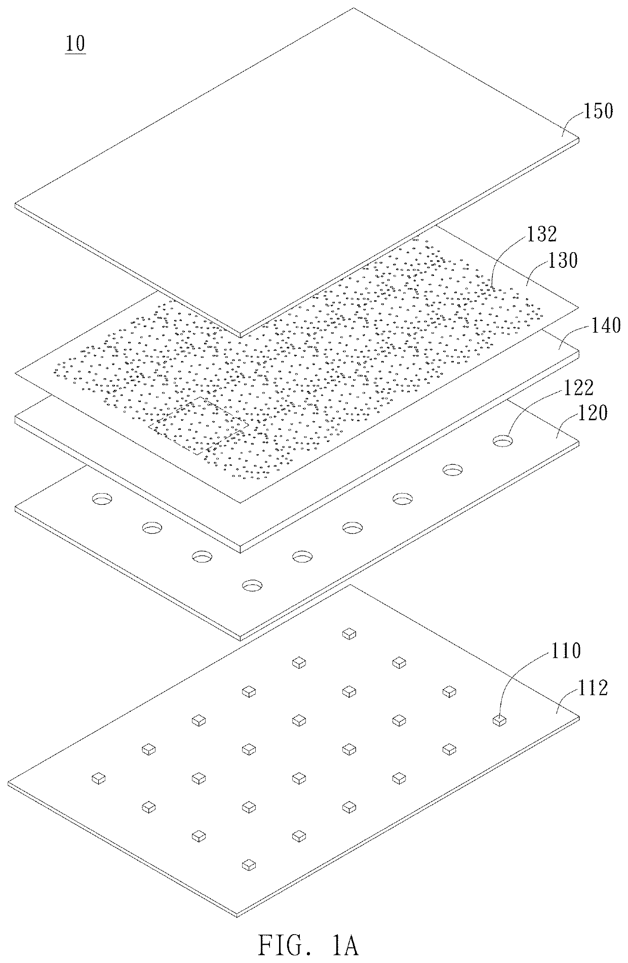
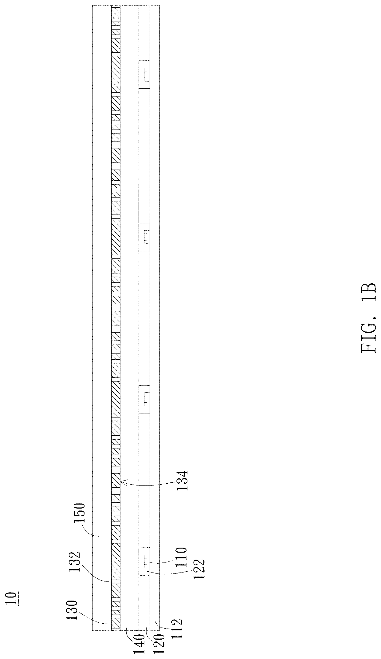
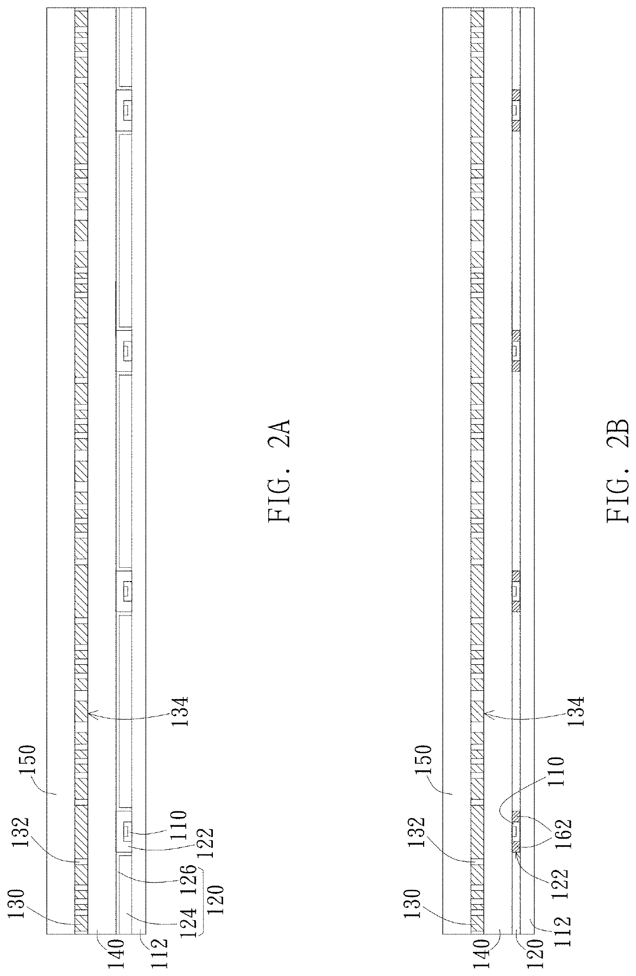
[0034]In the drawings, the thickness of layers, films, panels, regions, etc., are exaggerated for clarity. Like reference numerals designate like elements throughout the specification. It will be understood that when an element such as a layer, film, region, or substrate is referred to as being “on” or “connected to” another element, it can be directly on or connected to the other element or intervening elements may also be present. In contrast, when an element is referred to as being “directly on” or “directly connected to” another element, there are no intervening elements present.

[0035]In addition, the relative terms such as “below” or “bottom” and “above” or “top” may be used herein to describe the relationship of one element to another, as illustrated. It will be understood that the relative terms are intended to encompass different orientations of the device in addition to the orientation shown in the drawings. For example, if the device in the drawings is turned over, the ele...


PUM

PropertyMeasurementUnit
transmittanceaaaaaaaaaa
thicknessaaaaaaaaaa

Abstract

A display device includes a display panel and a backlight module disposed under the display panel. The display panel has a display area and a light-blocking layer disposed around the display area. The backlight module includes a plurality of light sources, a reflector disposed corresponding to the light sources, an optical modulation film disposed above the light sources and the reflector, a diffusion member sandwiched between the reflector and the optical modulation film, and a diffusion plate disposed on one side of the optical modulation film opposite to the diffusion member, wherein the optical modulation film is sandwiched between the diffusion plate and the diffusion member, and the diffusion member has a transmittance of 65%˜85%.

Description

BACKGROUND OF THE INVENTION1. Field of the Invention[0001]The invention generally relates to a display device and a backlight module thereof. Particularly, the invention relates to a display device and a backlight module, which reduces the possibility of deformation of the optical modulation film by a thinning design.2. Description of the Prior Art[0002]With the consumer preferences and the increase in demand, the thinning of display devices has become an inevitable trend, and the backlight module is one of the major targets for reducing the thickness of the display device. Because the backlight module needs a light-mixing space, an air gap of more than 1 mm is usually maintained above and below the optical film. When the heat dissipation is poor, the optical film is prone to become waving due to deformation, impairing the optical quality of the display devices. When the backlight module becomes thinner, the local deformation or bending of the optical film becomes more obvious, seve...

Claims


Application Information

Patent Timeline
Patent Type & Authority Patents(United States)
IPC IPC(8): G02F1/13357
CPCG02F1/133606G02F1/133603G02F1/133605G02F2202/28G02F1/133611
Inventor CHEN, MING-LUNGHSU, MING-CHUNCHEN, CHENG-CHUANWU, CHIH-KANG
Owner AU OPTRONICS CORP
Why Eureka
Try Eureka