Optical fiber

a technology of optical fibers and fibers, applied in the field of optical fibers, can solve the problems of bending loss in optical signals transmitted by optical fibers, and achieve the effect of low bending loss

Active Publication Date: 2021-08-24
SUMITOMO ELECTRIC IND LTD
View PDF26 Cites 0 Cited by
  • Summary
  • Abstract
  • Description
  • Claims
  • Application Information

AI Technical Summary

Benefits of technology

[0030]According to the present disclosure, it is possible to provide an optical fiber with a low bending loss.

Problems solved by technology

When an optical fiber is bent, bending loss occurs in an optical signal transmitted by the optical fiber.

Method used


Image

  • Optical fiber
  • Optical fiber
  • Optical fiber

Examples


Embodiment Construction

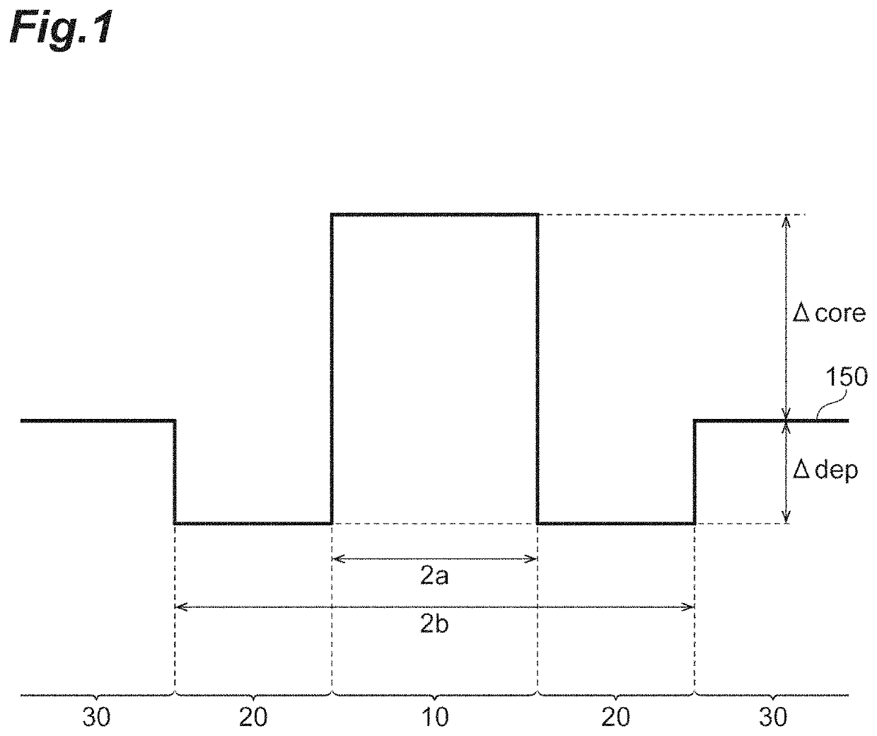
[0019]A parameter called a caustic radius is important in the examination of the bending loss of an optical fiber. The caustic radius will be described with reference to FIGS. 1 and 2. FIG. 1 is a diagram illustrating an example of a refractive index profile of an optical fiber. This optical fiber has a W-shaped refractive index profile 150. That is, this optical fiber includes a core 10, an inner cladding 20 surrounding the core 10, and an outer cladding 30 surrounding the inner cladding 20. The inner cladding 20 has a refractive index smaller than that of the core 10. The outer cladding 30 has a refractive index smaller than that of the core 10 and greater than that of the inner cladding 20.

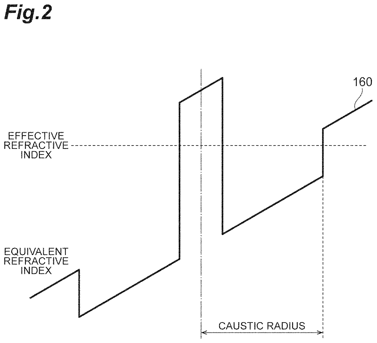
[0020]FIG. 2 is a diagram illustrating an equivalent refractive index profile 160 for handling an optical fiber bent at a certain radius as a linear waveguide. When the optical fiber is bent, the propagation distance of light is longer on the outside of the bend of the optical fiber than on the...


PUM

PropertyMeasurementUnit
wavelengthaaaaaaaaaa
bending radiusaaaaaaaaaa

Abstract

An optical fiber according to an embodiment includes: a core; an inner cladding surrounding the core and having a refractive index smaller than a refractive index of the core; an outer cladding surrounding the inner cladding and having a smaller refractive index than the refractive index of the core and having a refractive index greater than the refractive index of the inner cladding, in which a ratio of a caustic radius to a MAC-value (caustic radius / MAC-value) at a bending radius of 10 mm at a wavelength of 1625 nm is 2.70 μm or more.

Description

CROSS-REFERENCE TO RELATED APPLICATIONS[0001]This application is a continuation application of PCT / JP2019 / 007356 claiming the benefit of priority of the Japanese Patent Application No. 2018-040665 filed on Mar. 7, 2018, the entire contents of which are incorporated herein by reference.TECHNICAL FIELD[0002]The present disclosure relates to an optical fiber.[0003]This application is based upon and claims the benefit of priority from Japanese application No. 2018-040665, filed on Mar. 7, 2018, the entire contents of which is incorporated herein by reference.BACKGROUND ART[0004]In addition to in optical components and optical modules using optical fibers, optical fibers bent with a small radius are often installed particularly in the access system in optical fiber networks. When an optical fiber is bent, bending loss occurs in an optical signal transmitted by the optical fiber. This leads to a demand for an optical fiber having a low bending loss. Bending loss is the loss caused by bend...

Claims


Application Information

Patent Timeline
Patent Type & Authority Patents(United States)
IPC IPC(8): G02B6/02G02B6/036
CPCG02B6/03627G02B6/02004G02B6/02395G02B6/03644G02B6/03622
Inventor SUZUKI, MASATOKAWAGUCHI, YUKIYAMAMOTO, YOSHINORIHASEGAWA, TAKEMI
Owner SUMITOMO ELECTRIC IND LTD
Why Eureka
Try Eureka