Plastic optical fiber and production method thereof

a technology of optical fiber and production method, applied in the field of plastic optical fiber, can solve the problems of increasing the optical transmission loss in the pofs, the pofs is not suitable for optical transmittance for long distance, and the transmission loss is increased, so as to reduce the bending loss

Inactive Publication Date: 2009-03-24
FUJIFILM CORP
View PDF8 Cites 1 Cited by
  • Summary
  • Abstract
  • Description
  • Claims
  • Application Information

AI Technical Summary

Benefits of technology

[0011]In view of the foregoing, an object of the present invention is to provide a POF in which a bending loss caused by bending stress and light scattering are reduced. Another object of the present invention is to provide a production method of the above POF without reduction in productivity.
[0018]According to the present invention, it becomes possible to provide the POF which transmits the light with low bending loss, while preventing light scattering and light leakage to the outside caused by bending. Further, the method for continuously producing the POF with the reduced bending loss is achieved.

Problems solved by technology

However, on the other hand, these advantages increase the optical transmission losses in the POFs, making the POFs not suitable for optical transmittance for long distance.
However, on the other hand, bending causes transmission losses (hereinafter referred to as bending losses).
The bending losses significantly lower the function of the POFs as the optical transmission media.
As a result, the bending loss cannot be reduced.
On the other hand, in the case non-crystalline fluorine-containing polymer is used for forming the outer layer, it is inferior in solvent resistance to a monomer.
As a result, it becomes difficult to form a core which will be the optical transmission path with a monomer inside the outer layer.
In the case the cavities are formed between the POF and the protective layer, it is difficult to control shapes, sizes and conditions of the cavities.
In the case the resin foam layer is formed, it is difficult to control foam conditions in the resin foam.
However, it is difficult to reduce the bending losses namely the light leakage and / or the light scattering caused at the interface between the clad and the core.
In the case the diameter of the core which is the optical transmission path is extremely small, it becomes difficult to connect the POFs.
As a result, the workability is reduced.

Method used


Image

  • Plastic optical fiber and production method thereof
  • Plastic optical fiber and production method thereof
  • Plastic optical fiber and production method thereof

Examples


example

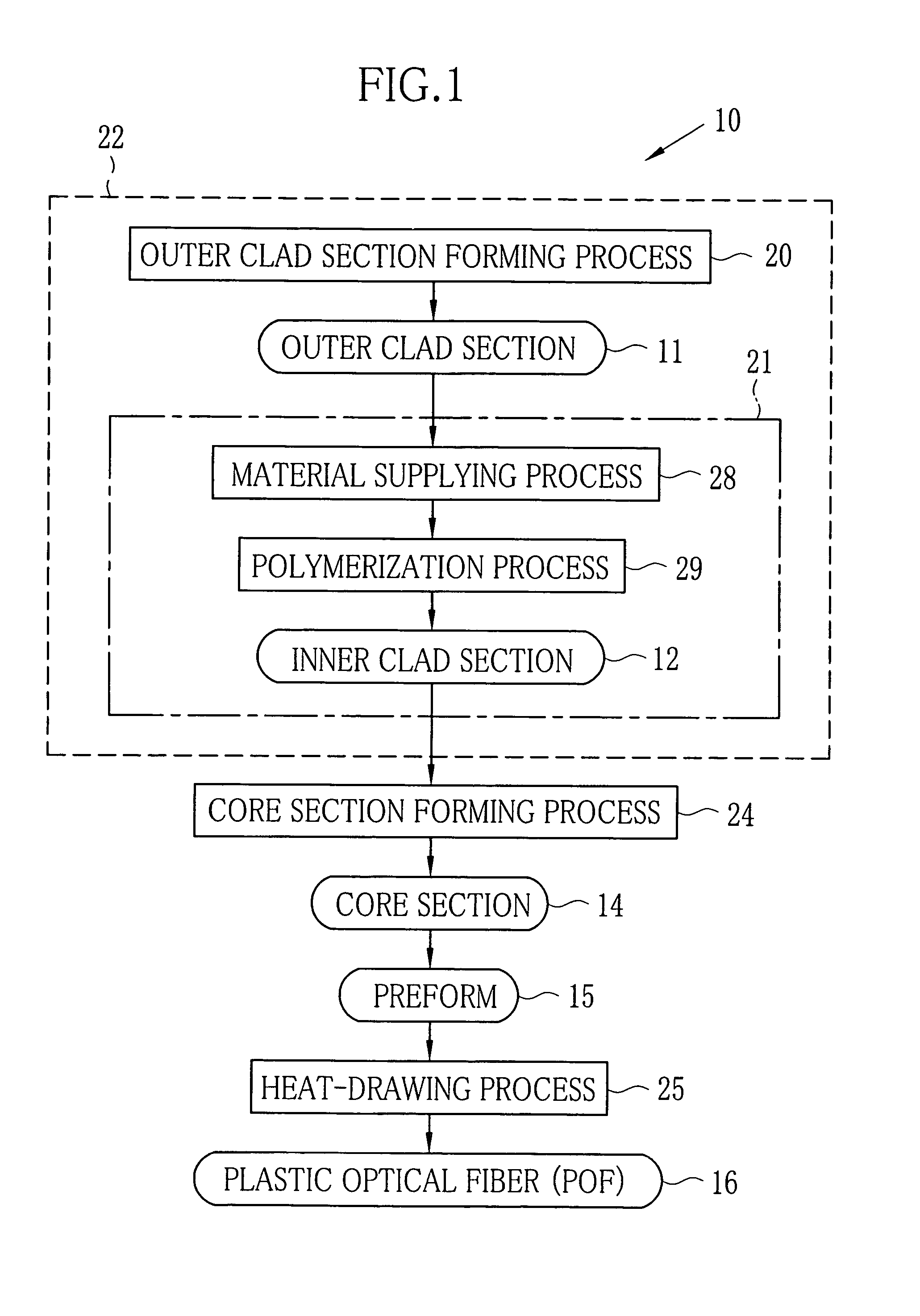
[0096]In the Example (in Experiments 1-1 to 1-3), three types of POFs 15 having different outer diameters are produced from the preforms 15 by changing conditions of heat-drawing. The preforms 15 were formed by the method described below. All of the produced POFs 15 were GI POFs.

experiment 1-1

[0097]By the melt-extrusion molding, the cylindrical outer clad section 11 was formed of PVDF having the molecular structure in which the number of the defect bonds of the successive CF2 units and successive CH2 units constitutes 4.5% with respect to the total number of the bonds of the CF2 units and CH2units. The outer clad section 11 had the inner diameter of 20 mm, the length of 905 mm, and the outer diameter of 20.5 mm. The average roughness Ra′ of the inner wall of the outer clad section 11 was 0.23 μm. A surface roughness meter (product name: VK-8500, produced by Keyence Corporation) was used for measuring the average roughness Ra′.

[0098]The inner clad section forming material was poured into the hollow portion of the outer clad section 11. The inner clad section forming material was 185 g of MMA in which the polymerization initiator and the chain transfer agents were mixed. The polymerization initiator was dimethyl-2,2′-azobis(2-methylpropionate) (product name: V-601, produce...

experiment 1-2

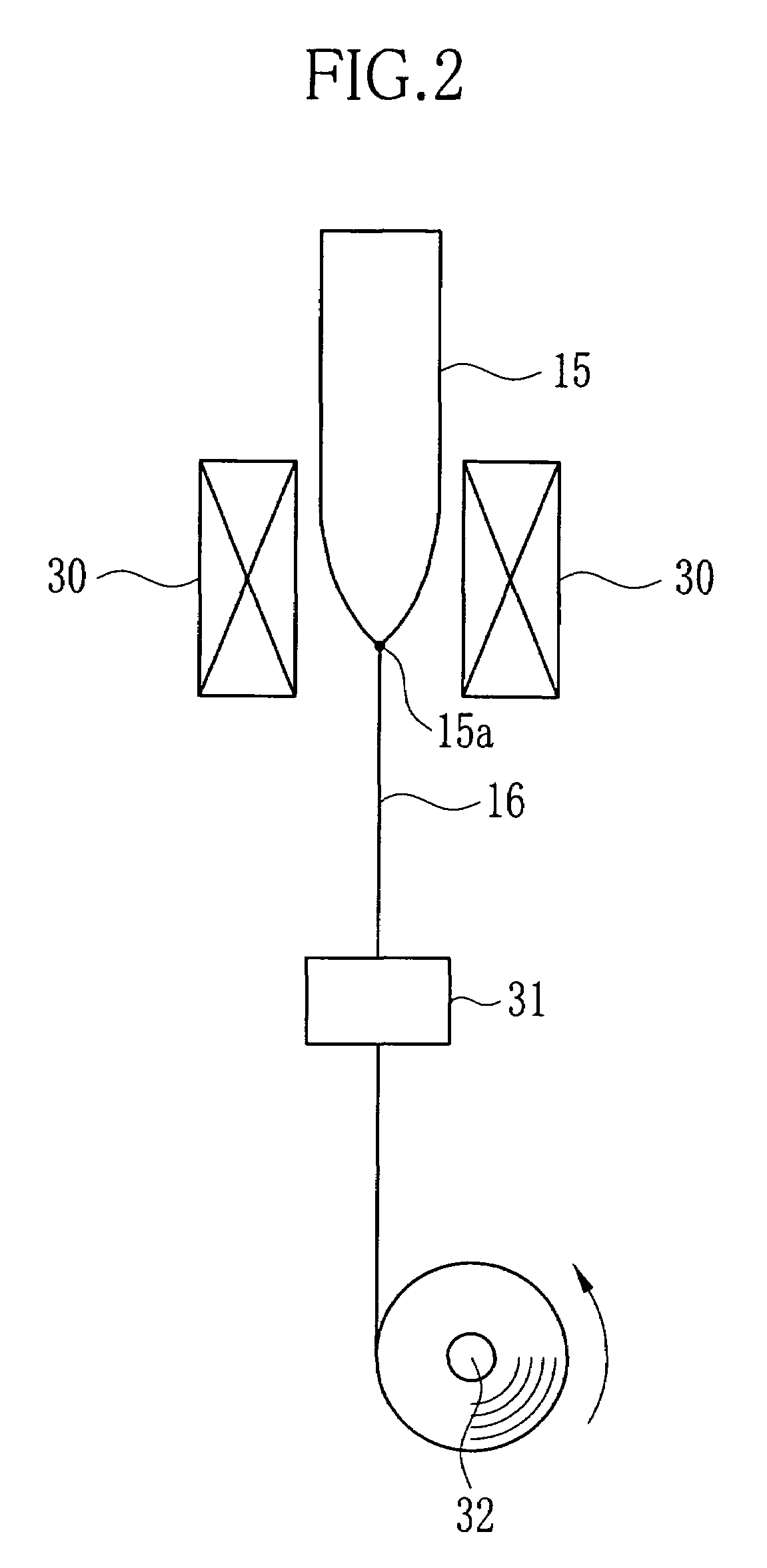
[0103]The preform 15 for producing the POF 16 was formed of the same material and by the same method as in the Experiment 1-1. The preform 15 having the outer clad section 11 with Ra′ of 0.23 μm was heat-drawing in the furnace 30. The produced POF 16 had the outer diameter of 470 μm. The outer diameter of the inner clad 42 was 440 μm. Ra of the outer clad 41 of the produced POF 16 was 0.07 μm. The bending loss of the POF 16 was extremely low (0.015 dB).


PUM


Abstract

A cylindrical outer clad section is formed by melt-extrusion molding of polyvinylidene fluoride (PVDF) having a molecular structure in which the number of defect bonds of successive CF2 units and successive CH2 units constitutes not less than 4% with respect to a total number of bonds of CF2 units and CH2 units. Next, an inner clad section forming material is poured into a hollow portion of the outer clad section and polymerized to form a cylindrical inner clad section. A core section forming material is filled in a hollow portion of the inner clad section and polymerized to form a core section. Thus, a preform is fabricated. The preform is heat-drawn to obtain a POF. The POF has an outer clad in which small spherocrystals are formed. Average roughness Ra of an inner wall of the outer clad is less than 0.10 μm.

Description

BACKGROUND OF THE INVENTION[0001]1. Field of the Invention[0002]The present invention relates to a plastic optical fiber and a production method thereof.[0003]2. Description of the Related Art[0004]Plastic optical fibers, hereinafter referred to as POFs have advantages such as lightweight, excellent workability, and low production cost compared to quartz based POFs due to being formed of plastics. The POFs also have other advantages such as easily increasable diameter, and high bending tolerance due to high flexibility. However, on the other hand, these advantages increase the optical transmission losses in the POFs, making the POFs not suitable for optical transmittance for long distance. The POFs attract attention as light transmission media for a short distance such as for domestic use, vehicle-mounted use, or the like in which the transmission losses are not concerned.[0005]The POF is constituted of a core and a clad. The clad is formed on the outer periphery of the core and has...

Claims


Application Information

Patent Timeline
Patent Type & Authority Patents(United States)
IPC IPC(8): G02B6/00G02B6/02
CPCB29D11/00663G02B6/02038G02B6/0281G02B6/03633G02B6/0288
Inventor SHIROKURA, YUKIOYAMAKI, KOUSUKE
Owner FUJIFILM CORP
Why Eureka
Try Eureka